Method of building a floor for a boiler cage

a technology of boiler cage and floor, which is applied in the direction of boiler supporting/setting arrangements, foundation engineering, building repairs, etc., can solve the problems of deteriorating efficiency, increasing the difficulty of lifting huge blocks with the crane, and reducing the construction cost. , to achieve the effect of facilitating the construction of the floor, reducing the construction cost and shortening the construction period

Inactive Publication Date: 2008-02-07
MITSUBISHI POWER LTD
View PDF21 Cites 10 Cited by
  • Summary
  • Abstract
  • Description
  • Claims
  • Application Information

AI Technical Summary

Benefits of technology

[0015]The objective of the present invention is to mend the prior-art problems, by making the erection of the boiler cage floors more readily even after the installation o

Problems solved by technology

Because of this reason, there are problems that arise the efficiency deteriorates when importing and lifting various components of floors 13 by utilizing the crane since the eco-hopper 9 becomes the obstacle of the lifting operation.
However, if a block method of construction described in the Japanese Patent Number 2,932,818 is applied

Method used


Image

  • Method of building a floor for a boiler cage
  • Method of building a floor for a boiler cage
  • Method of building a floor for a boiler cage

Examples


Embodiment Construction

[0034]The embodiments of the present invention are described below with reference to the accompanying drawings.

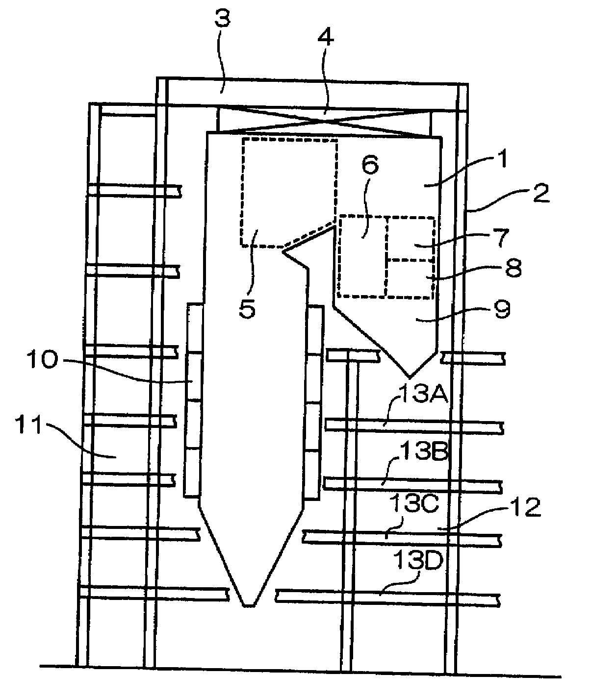
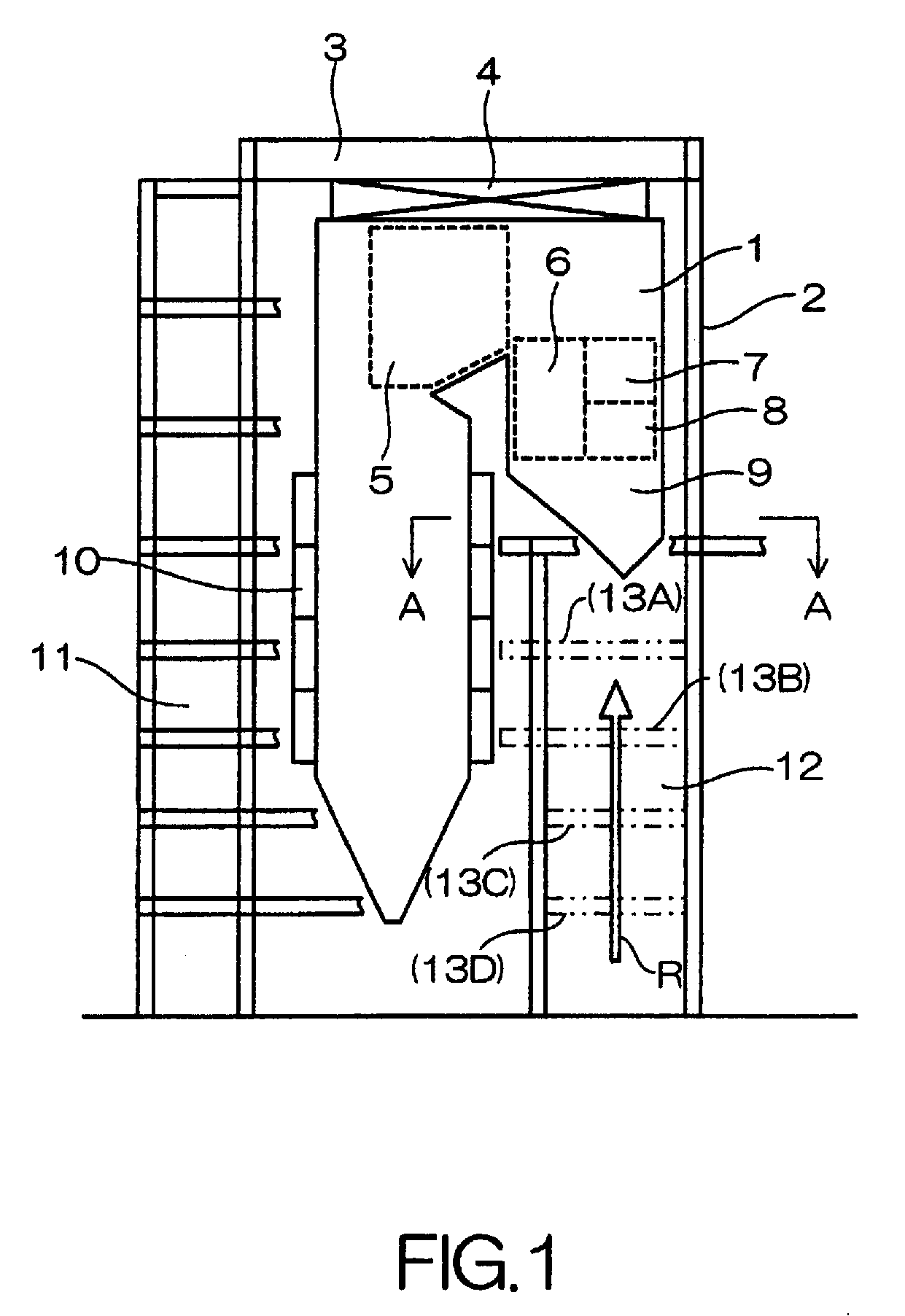
[0035]FIG. 1 is the side view which illustrated main architecture of a large-scale boiler for thermal power plant just before the implementation of the present invention. A Boiler main body 1 is hung from a sky beam 3 of a boiler frame 2 through hanging portion 4.

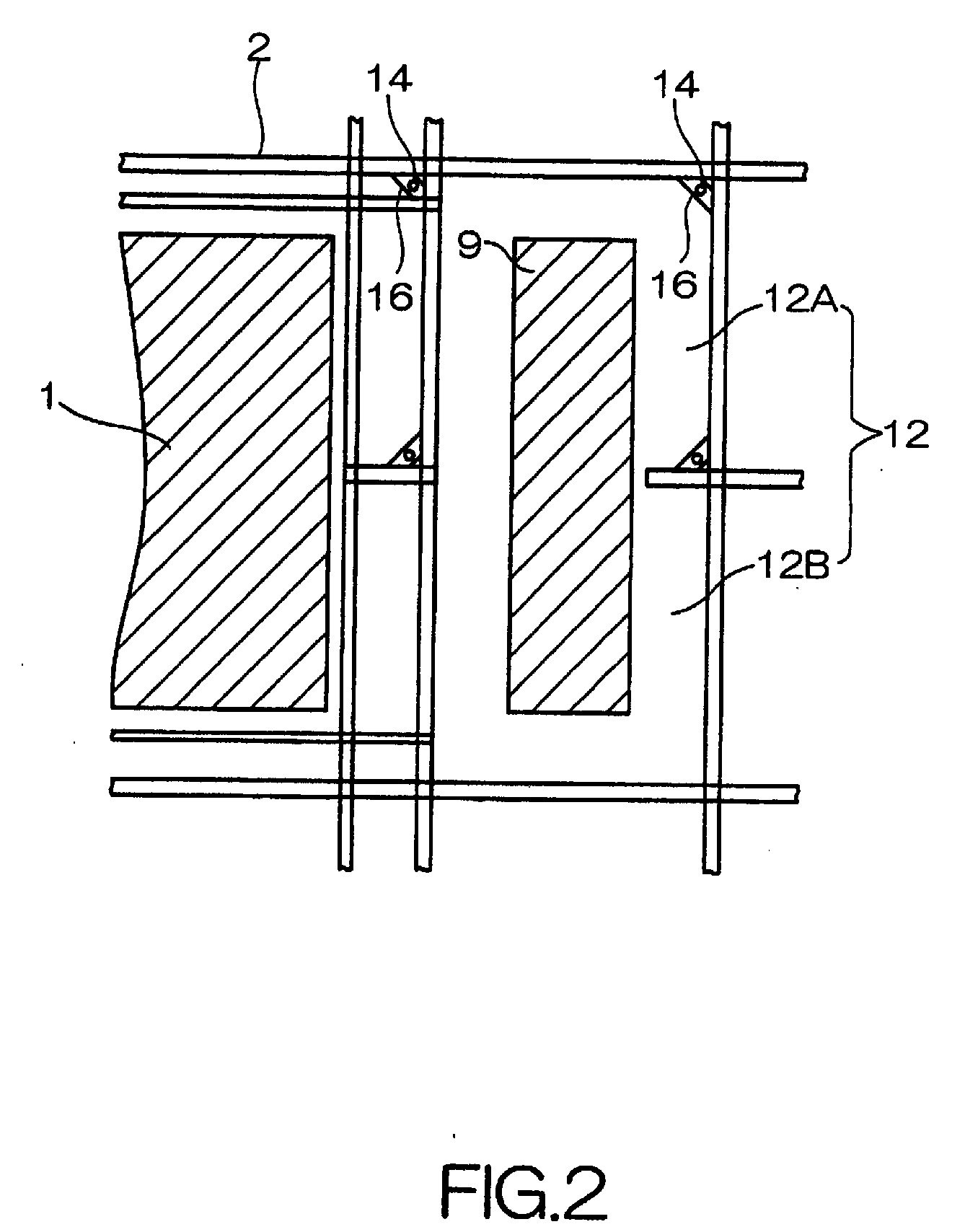
[0036]Inside of boiler main body 1, a second and third super-heater 5, a reheater 6, a primary super-heater 7, an economizer 8 are placed; and the lower parts of the re-heater 6 and the economizer 8 are formed to be an eco-hopper 9. Plural of wind boxes 10 are arranged to a furnace wall of the boiler main body 1. A left area 11 of the boiler frame 2 is the area where coal bunker is positioned.

[0037]The area below the eco-hopper 9 is assumed as a cage part 12. Until installation of various equipments such as a re-heater 6, a primary super-heater 7, a economizer 8, and an eco-hopper 9 are completed, a lifting root R ...


PUM


Abstract

The floor, which became a block, can easily be attached to the designated floor position, so that the reduction of both the construction cost and the construction period are achieved. It is a method of building the plural floors on the part of the boiler cage part, and one floor 13A is built on a lifting frame 18 put on the ground, and the floor 13A and the lifting frame 18 are both jacked up by jacks 14. Subsequently the lifting frame 18 which separated the floor 13A is jacking down and returned to the ground. Plural floors are built for lower floor from upper floor one after another by repeating such a series of steps.

Description

RELATED APPLICATION [0001]The present application claims priority under the Paris Convention from Japanese Application 2006-212384 filed on Aug. 3, 2006, the contents of which are hereby incorporated by reference into this application.BACKGROUND[0002]1. Field of the Invention[0003]The present invention relates to a method of a boiler cage floors and more specifically to a method of the construction of boiler cage floors that is preferred for the construction of a large-sized boiler for thermal power plant.[0004]2. Related Art[0005]FIG. 9 is a side view illustrating main constitution of a large-sized boiler for thermal power generator. A boiler frame 2 taking main body of a boiler 1 is the gigantic structure that bearing height reaches 60-100 m. The boiler main body 1 is hung from a sky beam 3 of the boiler frame 2 through a hanging portion 4 to release the thermal expansion downward.[0006]Inside of boiler main body 1, a second and third super-heater 5, a re-heater 6, a primary super...

Claims


Application Information

Patent Timeline
IPC IPC(8): E04G23/06
CPCF22B37/24
Inventor NAKAMITSU, KAZUHITOKAWAGUCHI, SHIGEYOSHITAKESHITA, SHINICHIROUYOSHIDA, YUUSUKEYOKOI, YUUJIITAGAKI, HIROMISHINOHARA, SHOJIKOMATSU, KENSHIN
Owner MITSUBISHI POWER LTD
Why Eureka
Try Eureka