Blood Analysis Apparatus and Blood Analysis Method

Inactive Publication Date: 2008-02-07
NAT INST FOR MATERIALS SCI
View PDF4 Cites 17 Cited by
  • Summary
  • Abstract
  • Description
  • Claims
  • Application Information

AI Technical Summary

Benefits of technology

[0024] The present invention has been achieved in consideration of such circumstances, and it Is a first aspect of the invention to provide a blood analysis apparatus for performing blood plasma separation by centrifuge operation, which allows conveyance of the blood plasma and the c

Problems solved by technology

In general, such automated analysis apparatuses are available in medical institutions such as hospitals, and are large in size, and their operation is limited to those who are technically qualified.
In this regard, sensors for liquid position should be newly installed in the blood analysis apparatus or outside the apparatus, but addition of such controlling instruments or position sensors has been causing a problem of making the apparatus expensive.
Therefore, there has been a problem that even though the amount of the calibration solution remaining on the surface of the flow channel means or analyzing means is a trace amount, that amount of the residual calibration solution has an impact on the fluctuation of the concentrations of measured chemicals in an analysis apparatus in which the amount of the blood plasma introduced is minimal.
H

Method used


Image

  • Blood Analysis Apparatus and Blood Analysis Method
  • Blood Analysis Apparatus and Blood Analysis Method
  • Blood Analysis Apparatus and Blood Analysis Method

Examples


Embodiment Construction

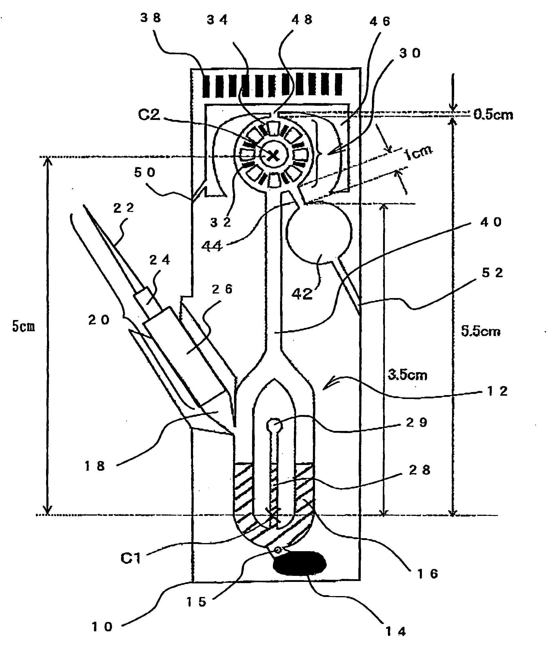
[0087]FIG. 4 is a schematic planar view of the blood analysis apparatus according to an embodiment of the present invention. Symbol 10 represents the substrate of a blood analysis apparatus formed longitudinally in the diagram, in which a substrate having a flow channel formed thereon is superposed on a substrate having sensor electrodes or wiring formed thereon, and the diagram indicates the internal flow channel structure. The upper and lower substrates are made of, for example, resins such as polyethylene terephthalate (PET) or polyearbonate (PC). Within the substrate 10, a corpuscle / plasma separating part 12 having a U-shaped flow channel at the lower end is disposed, and a corpuscle reservoir 14 as a corpuscle fraction storing part is formed at the bend of the lowest end. The upper part of the corpuscle reservoir 14 is used as a plasma fraction storing part 16 in which the blood plasma is fractionated as supernatant during centrifugation. Symbol 15 represents a backflow stop to...


PUM

PropertyMeasurementUnit
Magnetic fieldaaaaaaaaaa
Fractionaaaaaaaaaa

Abstract

A corpuscle/plasma separating part is disposed at the lower end of the substrate, and a sensor part connected to the corpuscle/plasma separating part is disposed at the upper end of the substrate, with a calibration solution reservoir being disposed on the lower side of the sensor part, and a calibration solution waste reservoir being disposed on the upper side of the sensor part. A first centrifugal axis is located upper to the corpuscle fraction storing part and lower to the plasma fraction storing part of the corpuscle/plasma separating part, while a second centrifugal axis is located within or close to the sensor part. Conveyance and discharge of the calibration solution can be carried out by performing centrifugation around the first centrifugal axis which is distant from the sensor part at a low speed of rotation, so that the centrifugal force exerted on the sensors would be small. During the centrifuge operation at a high speed of rotation for the separation of blood corpuscles, centrifugation can be performed around the second centrifugal axis so that the centrifugal force exerted on the sensors is small. Centrifuge operation allows separation of the blood corpuscles and blood plasma, and conveyance of the blood plasma and the calibration solution, as Well as certain discharge of the calibration solution from the sensors, thereby allowing precise analysis. Any damage in the sensors due to strong centrifugal force during the separation of blood corpuscles and blood plasma can be prevented.

Description

TECHNICAL FIELD [0001] The present invention relates to a blood analysis apparatus consisting of microgroove flow channels produced on a substrate made of insulating materials such as a quartz plate, a polymer resin plate or the like. In particular, the invention relates to the structure of the substrate and flow channels for performing conveyance of liquids such as a calibration liquid for an analytic sensor, blood, or the like, by means of centrifugal force, when a trace amount (a few μl or less) of blood is introduced to the groove flow channels on the substrate, is subjected to centrifuge, and is separated into the corpuscle component and the plasma component, and then the concentrations of various chemicals in the plasma component are measured. BACKGROUND ART [0002] Physical examination or diagnosis of disease states has been conventionally carried out by collecting a large amount, such as several cubic centimeters, of blood from a patient, and using the measurement values obta...

Claims


Application Information

Patent Timeline
IPC IPC(8): G01N33/48B04B5/02G01N27/26G01N35/00G01N27/333
CPCA61B5/1405B01L3/502753B01L2200/14B01L2200/148B01L2300/0645Y10T436/111666B01L2300/0864B01L2400/0409G01N27/4163G01N35/00693G01N2035/00495B01L2300/0816A61B5/150022A61B5/150213A61B5/150221A61B5/150389A61B5/150503A61B5/15142A61B5/15186
Inventor HORIIKE, YASUHIROOKI, AKIO
Owner NAT INST FOR MATERIALS SCI
Why Eureka
Try Eureka