Color filter and fabricating method thereof

a technology of color filter and fabrication method, applied in the field of color filter, can solve the problems of limited space utilization, considerable energy consumption, and inability to be perfect choices for users, and achieve the effect of improving display quality

Active Publication Date: 2008-02-07
AU OPTRONICS CORP
View PDF7 Cites 87 Cited by
  • Summary
  • Abstract
  • Description
  • Claims
  • Application Information

AI Technical Summary

Benefits of technology

[0043]When the color filter provided by the present invention is used in a transflective display, the relative ...

Problems solved by technology

However, it may not be a perfect choice for a user who simultaneously operates several computer terminals/displays, or from the view of environmental protection.
In view of the energy saving trend, the CRT has many problems, such as limited space utilization and considerable energy consumption.
In particular, the CRT is not capable of providing a solution to meet the light, slim, short and small tendency today and the demand on low power consumption.
Since the structu...

Method used


Image

  • Color filter and fabricating method thereof
  • Color filter and fabricating method thereof
  • Color filter and fabricating method thereof

Examples


first embodiment

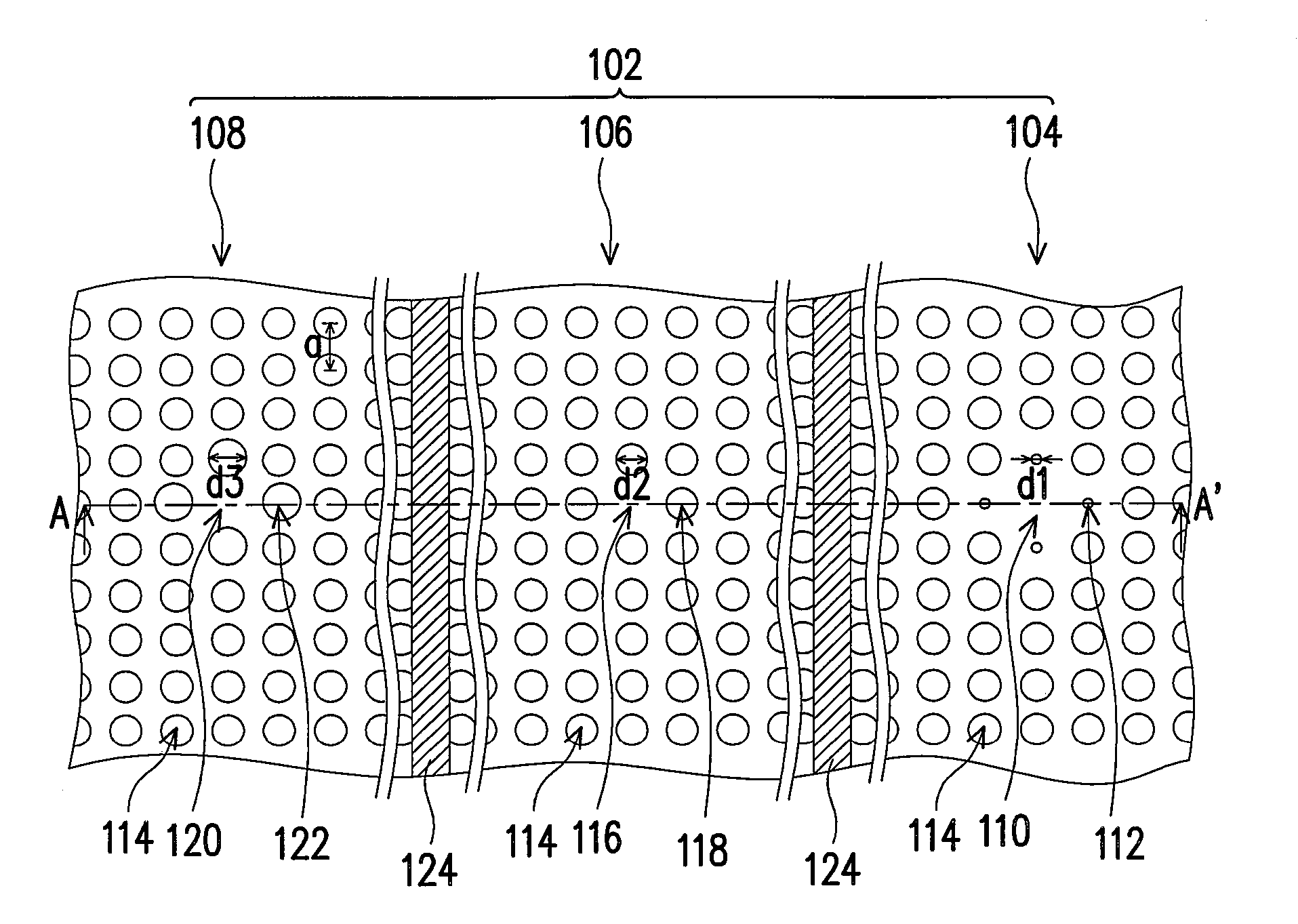
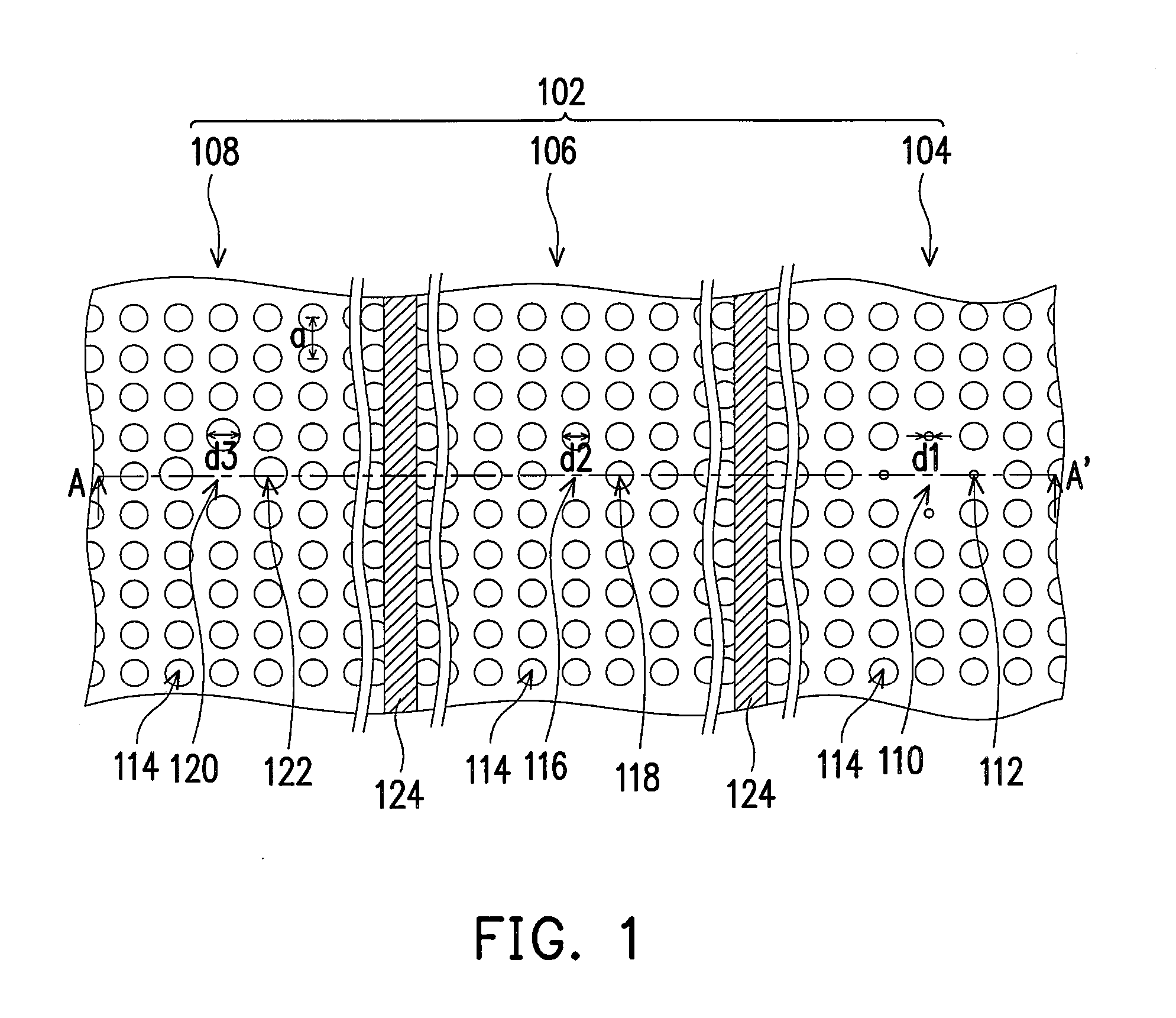
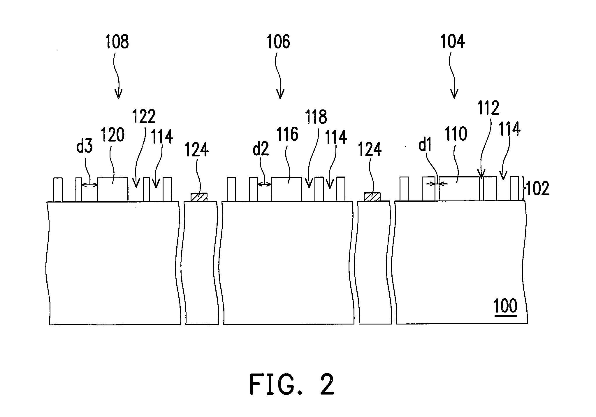
[0055]FIG. 1 is a top view of a color filter provided by the present invention. FIG. 2 is a cross-sectional drawing along plane A-A′ in FIG. 1.

[0056]Referring to FIGS. 1 and 2, a color filter includes a substrate 100 and a color filter layer 102. The substrate 100 is, for example, a transparent substrate, such as a glass substrate.

[0057]The color filter layer 102 is disposed on the substrate 100 and includes red photonic crystal structure 104, green photonic crystal structure 106 and blue photonic crystal structure 108. The material of the color filter layer 102 is dielectric material, for example, silicon nitride.

[0058]The red photonic crystal structure 104 includes a first defect resonance cavity 110, multiple first holes 112 surrounding the first defect resonance cavity 110 and multiple fourth holes 114 in a periodic arrangement and serves as a red filter unit.

[0059]The green photonic crystal structure 106 includes a second defect resonance cavity 116, multiple second holes 118 s...

second embodiment

[0071]FIG. 4 is a top view of a color filter provided by the present invention.

[0072]Referring to FIGS. 1 and 4, in the color filter of FIG. 1, the red photonic crystal structure 104, the green photonic crystal structure 106 and the blue photonic crystal structure 108 only have a first defect resonance cavity 110, a second defect resonance cavity 116 and a third defect resonance cavity 120, respectively, for providing the light with specific wavelength; therefore, the optical transmittance of the color filter layer 102 may not be sufficient, which affects the brightness of an LCD display.

[0073]However, in the color filter of FIG. 4, each red photonic crystal structure 104, green photonic crystal structure 106 and blue photonic crystal structure 108 respectively has multiple first defect resonance cavities 110, multiple second defect resonance cavities 116 and multiple third defect resonance cavities 120, where multiple defect resonance cavities are able to excite light with a same w...

third embodiment

[0076]FIG. 5 is a top view of a color filter provided by the present invention and FIG. 6 is a cross-sectional drawing along plane B-B′ in FIG. 5.

[0077]First, referring to FIGS. 5 and 6, a color filter includes a substrate 200, an organic material layer 232 and a color filter layer 202. The substrate 200 includes a reflective region 228 and a transmissive region 230. The substrate 200 is, for example, a transparent substrate such as a glass substrate.

[0078]The organic material layer 232 is disposed on the substrate 200 and in the reflective regions 228, which serves to make the optical path length of the light passing the reflective region 228 and that of the light passing the transmissive region 230 the same. The material of the organic material layer 232 is, for example, silicon nitride or silicon oxide and the like.

[0079]The color filter layer 202 is disposed on the substrate 200 and covers the organic material layer 232. The color filter layer 202 includes red photonic crystal s...


PUM


Abstract

A color filter including a substrate and a color filter layer is disclosed. The color filter layer is disposed on the substrate and includes a red photonic crystal structures, a green photonic crystal structure and a blue photonic crystal structure. The red photonic crystal structure includes a first defect resonance cavity and has multiple first holes surrounding the first defect resonance cavity. The green photonic crystal structure includes a second defect resonance cavity and has multiple second holes surrounding the second defect resonance cavity. The blue photonic crystal structure includes a third defect resonance cavity and has multiple third holes surrounding the third defect resonance cavity. Wherein, the hole diameter of the first holes is less than the hole diameter of the second holes, and the hole diameter of the second holes is less than the hole diameter of the third holes.

Description

CROSS-REFERENCE TO RELATED APPLICATION[0001]This application claims the priority benefit of Taiwan application serial no. 95128594, filed Aug. 4, 2006. All disclosure of the Taiwan application is incorporated herein by reference.BACKGROUND OF THE INVENTION[0002]1. Field of the Invention[0003]The present invention relates to a color filter, and more particularly, to a color filter using photonic crystal structures as the color filter layer thereof.[0004]2. Description of Related Art[0005]Because of its excellent display quality and economic advantage, cathode ray tubes (CRTs) have dominated the market in recent years. However, it may not be a perfect choice for a user who simultaneously operates several computer terminals / displays, or from the view of environmental protection. In view of the energy saving trend, the CRT has many problems, such as limited space utilization and considerable energy consumption. In particular, the CRT is not capable of providing a solution to meet the li...

Claims


Application Information

Patent Timeline
IPC IPC(8): G02F1/1335
CPCG02F2202/32G02F1/133516
Inventor WU, PEI-HSUNLAN, YING-CHEWANG, CHIH-HAWHSU, CHIA-YANG
Owner AU OPTRONICS CORP
Why Eureka
Try Eureka