Tunneling magnetic sensing element including enhancing layer having high Fe concentration in the vicinity of barrier layer and method for manufacturing tunneling magnetic sensing element

a magnetic sensing element and enhancing layer technology, applied in the field of magnetic sensing elements, can solve the problems of ineffective improvement of the above-described rate of resistance (r/r), unsatisfactory value of the inability to achieve the above-described rate of change in resistance (r/r), etc., to suppress the increase of the magnetostriction of the free magnetic layer, reduce the misfit of crystal

Active Publication Date: 2008-02-07
TDK CORPARATION
View PDF13 Cites 9 Cited by
  • Summary
  • Abstract
  • Description
  • Claims
  • Application Information

AI Technical Summary

Benefits of technology

[0029]In another aspect of the present disclosure, the enhancing region having a large Fe content is disposed on the side in contact with the barrier layer so as to improve the rate of change in resistance (ΔR / R). However, if only the enhancing region having a large Fe content is disposed, the magnetostriction λ of the above-described free magnetic layer increases. Therefore, the above-described enhancing region having a small Fe content is disposed on the side of the interface to the soft magnetic layer in order to decrease the magnetostriction λ. In this manner, the rate of change in resistance (ΔR / R) can increase and, in addition, an increase of the magnetostriction λ of the free magnetic layer can be suppressed as compared with those of the known tunneling magnetic sensing element.
[0043]The tunneling magnetic sensing element according to an aspect of the present disclosure can increase the rate of change in resistance (ΔR / R) without increasing the magnetostriction λ of the free magnetic layer.

Problems solved by technology

However, according to the known configuration, the value of the rate of change in resistance (ΔR / R) is unsatisfactory, and a further higher rate of change in resistance (ΔR / R) is not achieved while the magnetostriction of the free magnetic layer is controlled at a low level.
However, the above-described rate of change in resistance (ΔR / R) has not been able to be improved effectively.
However, there is no description about the rate of change in resistance, and it is not clear whether a high rate of change in resistance can be obtained, even when the magnetostriction can be decreased.
However, unexamined Japanese Patent Application Publication Nos. 2005-191312, 2003-060263, and 2006-128410 relate to spin-valve magnetoresistive elements, and do not relate to the relationship between the Fe content of the enhancing layer formed from Co—Fe and the rate of change in magnetoresistance or the magnetostriction with respect to the tunneling magnetic sensing element.

Method used


Image

  • Tunneling magnetic sensing element including enhancing layer having high Fe concentration in the vicinity of barrier layer and method for manufacturing tunneling magnetic sensing element
  • Tunneling magnetic sensing element including enhancing layer having high Fe concentration in the vicinity of barrier layer and method for manufacturing tunneling magnetic sensing element
  • Tunneling magnetic sensing element including enhancing layer having high Fe concentration in the vicinity of barrier layer and method for manufacturing tunneling magnetic sensing element

Examples


examples

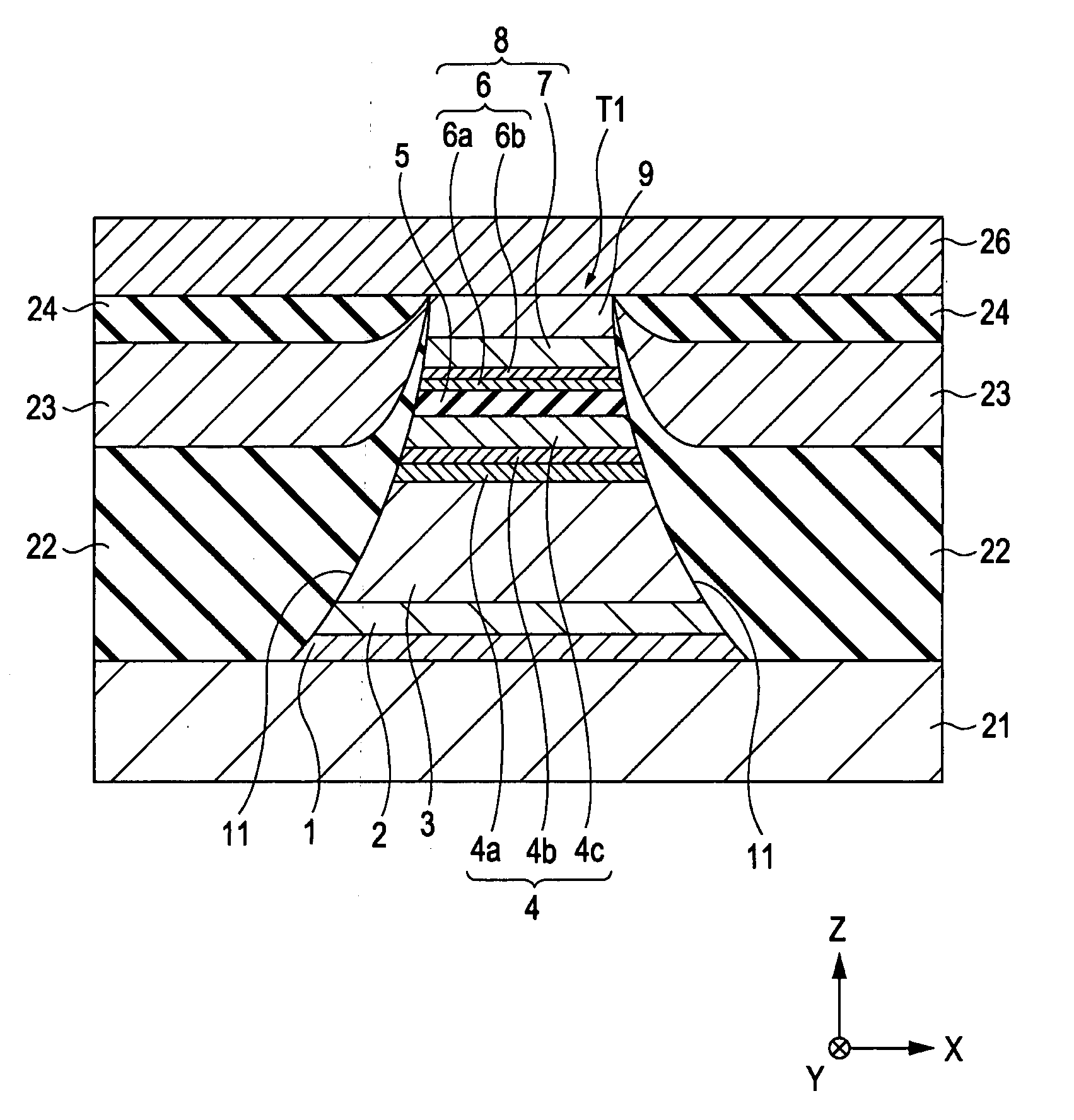
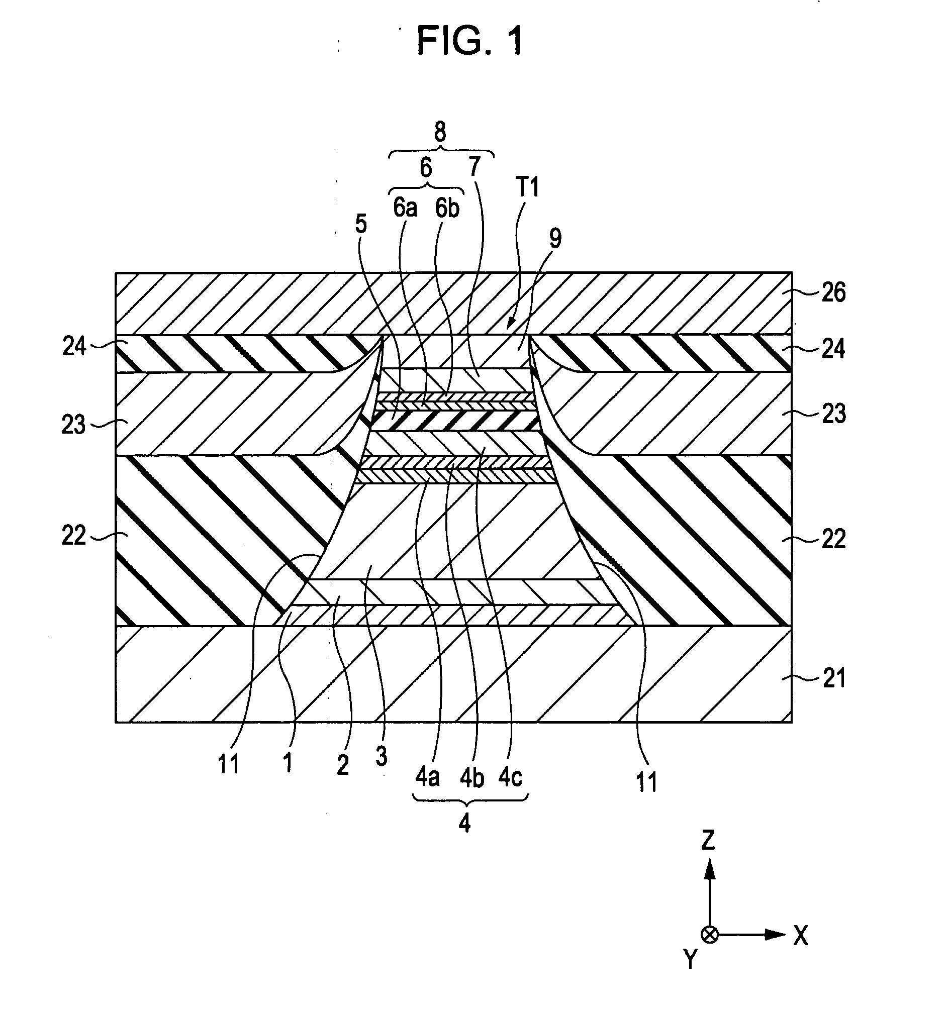
[0120]The tunneling magnetic sensing element as shown in FIG. 1 was formed.

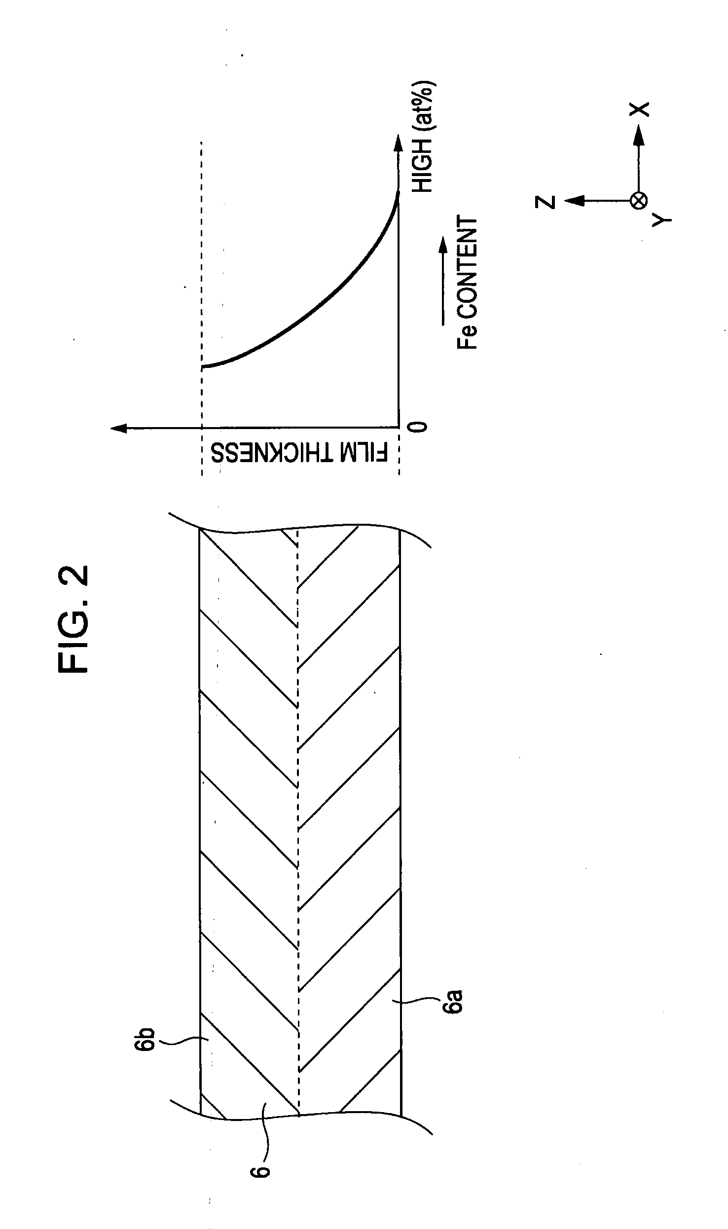
[0121]In the laminate T1, the order of lamination was substrate layer 1: Ta (80) / seed layer 2: NiFeCr (50) / antiferromagnetic layer 3: IrMn (70) / pinned magnetic layer 4 first pinned magnetic layer 4a: Co70Fe30 (14) / nonmagnetic intermediate layer 4b: Ru (8.5) / second pinned magnetic layer 4c: Co90Fe10 (18)] / barrier layer 5 / free magnetic layer 8 [first enhancing layer 6a / second enhancing layer 6b / soft magnetic layer 7] / protective layer 9: Ta (200) from the bottom. A numerical subscript is expressed in atomic percent, and a numerical value in parentheses indicates an average film thickness in Å.

[0122]After the laminate T1 was formed, an annealing treatment was performed at 270° C. for 3.5 hours. It is believed that the first enhancing layer 6a and the second enhancing layer 6b were principally maintained to be two layers.

[0123]The examples in the case where the above-described barrier layer 5 is Ti—O will be descr...


PUM

PropertyMeasurementUnit
temperatureaaaaaaaaaa
magnetizationaaaaaaaaaa
external magnetic fieldaaaaaaaaaa

Abstract

A tunneling magnetic sensing element is provided, in which an increase in the magnetostriction of a free magnetic layer is reduced and the rate of change in resistance is high. A laminate T1 constituting the tunneling magnetic sensing element includes a portion in which a pinned magnetic layer, a barrier layer, and a free magnetic layer are disposed in that order from the bottom. An enhancing layer disposed on the barrier layer side of the free magnetic layer includes a first enhancing layer on the barrier layer side and a second enhancing layer on the soft magnetic layer side, and the Fe content of a CoFe alloy constituting the first enhancing layer is specified to be larger than the Fe content of the CoFe alloy of the second enhancing layer.

Description

RELATED APPLICATIONS[0001]This application claims benefit of priority under 35 U.S.C. § 119 to Japanese Patent Application No. 2006-212237 filed on Aug. 3, 2006, which is hereby incorporated by reference.BACKGROUND[0002]1. Field of the Disclosure[0003]The present disclosure relates to a magnetic sensing element through the use of a tunnel effect, the magnetic sensing element being mounted on a magnetic playback apparatus, e.g., a hard disk apparatus, or other magnetic sensing apparatuses. In particular, the present disclosure relates to a tunneling magnetic sensing element having a high rate of change in resistance (ΔR / R) free from increase in a magnetostriction value λ of a free magnetic layer. Additionally, the tunneling magnetic sensing element exhibits excellent magnetic detection sensitivity and stability, as well as a method for manufacturing the tunneling magnetic sensing element.[0004]2. Description of the Related Art[0005]In a tunneling magnetic sensing element (tunneling m...

Claims


Application Information

Patent Timeline
Patent Type & Authority Applications(United States)
IPC IPC(8): G11B5/127G11B5/33
CPCB82Y10/00B82Y25/00B82Y40/00G01R33/093G01R33/098H01L43/12G11B5/3909H01F10/3254H01F41/305H01L43/08G11B5/3906H10N50/10H10N50/01
Inventor NAKABAYASHI, RYOHASEGAWN, NAOYASAITO, MASAMICHIISHIZONE, MASAHIKOIDE, YOSUKESEINO, TAKUYANISHIMURA, KAZUMASA
Owner TDK CORPARATION
Why Eureka
Try Eureka