Fluid conveyance system and fluid conveyance device

a fluid conveyancing system and fluid technology, applied in the direction of positive displacement liquid engines, instruments, machines/engines, etc., can solve the problems of not being able to individually recognize difficult to change the type of chemical fluid administration, and not being able to mount the fluid conveyancing device inside the body of a small animal, etc., to achieve the effect of increasing safety

Inactive Publication Date: 2008-02-07
SEIKO EPSON CORP
View PDF14 Cites 32 Cited by
  • Summary
  • Abstract
  • Description
  • Claims
  • Application Information

AI Technical Summary

Benefits of technology

[0016]According to the fluid conveyance system, individual identification data being input into the memory device of the micro pump module, as it is possible for the discharge data processing device, via the communication device, to read and recognize the identification data of the micro pump module, it not being necessary for a fluid conveyance system user (who may be referred to hereafter as a user) to artificially identify the micro pump module, it is possible to prevent a kind of mistake such as inputting erroneous discharge data into the micro pump module to be used, and driving it. This has a benefit of being able to prevent an effect which cannot be ignored when using the fluid conveyance system in medical treatment, a living organism experiment, or the like.
[0019]The correction coefficient for correcting the discharge fluctuation due to the fluctuation in the inner diameter of the tube is expressed as a ratio between a design tube inner diameter (the inner diameter can be converted into a sectional area over which a fluid flows) and an inner diameter of a tube used in a fluid conveyance device to be driven, or as a ratio between a discharge amount of a fluid conveyance device which includes a tube to be taken as a standard, and a discharge amount of the fluid conveyance device to be driven. Consequently, as the fluid conveyance device is driven by discharge data in which the fluctuation in the inner diameter of the individual tube to be driven has been corrected, it is possible to eliminate an effect of the fluctuation in the inner diameter of the tube on the discharge amount of the fluid.
[0021]Furthermore, by mounting the fluid conveyance device to be driven on the discharge data processing device and the communication device, the discharge data processing device being able to recognize the identification data, it is unnecessary for the user to input the identification data into the discharge data processing device, so there is also a benefit of being able to eliminate a bother of inputting, and prevent an input error.
[0025]Furthermore, as it is possible to set the discharge speed and discharge time in accordance with the remaining capacity of the battery, it is possible to prevent the battery capacity expiring and the fluid conveyance device stopping while being used, and to increase safety.
[0030]In a case of assuming that the previously described memory device storing the identification data is an RAM (Random Access memory) or the like, it is conceivable that the identification data could be deleted by an effect of static electricity or the like. However, by displaying the identification data on the display portion by the barcode or the QR code, and recognizing them with the reader, it is possible to prevent the identification data from being deleted by the effect of the static electricity or the like.
[0032]The individual identification data being input into the memory device of the micro pump module, as it is possible for the discharge data processing device, via the communication device, to read and recognize the identification data of the micro pump module, it not being necessary for the user to artificially identify the micro pump module, it is possible to prevent a kind of mistake such as inputting erroneous discharge data into the micro pump module to be used, and driving it.

Problems solved by technology

However, discharge conditions once set being fixed, there is a problem in that it is difficult to change a type of usage and conditions of a chemical fluid administration at will, and set a fluid discharge amount.
Also, according to U.S. Pat. No. 3,737,251, it is possible, by providing switches for adjusting a discharge amount of a fluid, a display and a peristaltic pump, on a housing, to adjust the discharge amount but, as the miniature peristaltic pump, switches and display are placed on the housing, miniaturization is difficult with this kind of configuration, and it is not possible to mount it inside a body of a small animal with an object of a new chemical development or the like.
Also, in both the previously described Japanese Patent 3177742 and U.S. Pat. No. 3,737,251, a plurality of fluid conveyance devices existing, when selectively using a fluid conveyance device with pre-set discharge conditions, it is not possible to individually recognize the fluid conveyance device.
Consequently, it being conceivable that a human error occurs whereby a fluid conveyance system user (referring to a user) uses a fluid conveyance device in which wrong discharge conditions have been set, there is a kind of problem in that there will be serious consequences when using in medical treatment or the like.
Also, when using a battery or the like as a power source, although, when stopping the fluid conveyance device during use, then reusing it, it is necessary to drive with a discharge condition program corresponding to a remaining capacity of the battery, in the previously described Japanese Patent 3177742 and U.S. Pat. No. 3,737,251, there not being that kind of function, it is not possible to repeatedly reuse the fluid conveyance device until the battery capacity expires.
Furthermore, in the event that a remaining amount of a battery capacity of each of a plurality of fluid discharge devices differs, as it is not possible to recognize a battery remaining capacity for one fluid discharge device, it being unclear how much longer it is possible to drive the relevant fluid discharge device, there is a problem in that it is not possible to efficiently use the fluid conveyance device, such as by re-driving.

Method used


Image

  • Fluid conveyance system and fluid conveyance device
  • Fluid conveyance system and fluid conveyance device
  • Fluid conveyance system and fluid conveyance device

Examples


embodiment 1

[0104]In Embodiment 1, a description will be given exemplifying with a fluid conveyance system which employs a micro pump module (which may be referred to hereafter as a micro pump), mountable inside a living organism, which realizes a discharge of a minute amount of a fluid (which may be referred to as a chemical liquid) in microliter (μl) units.

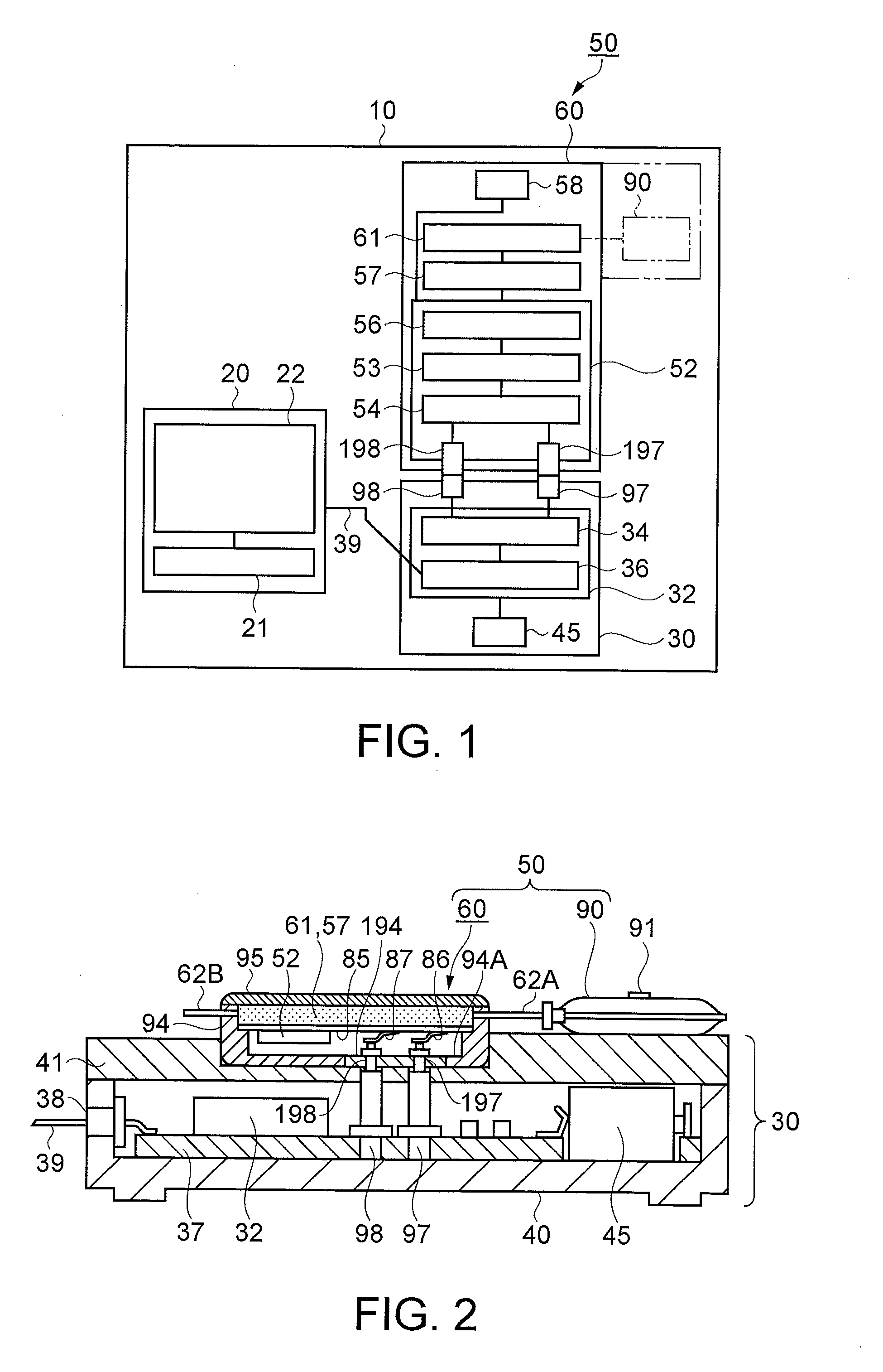
[0105]FIG. 1 is a block illustration showing one example of the configuration of the fluid conveyance system according to Embodiment 1. In FIG. 1, the fluid conveyance system 10 is configured of, as its basic components, a discharge data processing device 20 (which may be referred to hereafter as a PC (Personal Computer) 20), a communication device 30, and a fluid conveyance device 50.

[0106]An operating portion 21, as an input device which inputs drive conditions of the fluid conveyance device 50, a display 22, which displays the input drive conditions and a drive result, as well as a calculation processing function, a memory function, and ...

embodiment 2

[0273]Continuing, a description will be given of a fluid conveyance device and a fluid conveyance system according to an embodiment 2. The embodiment has a feature of expressing the identification data by a barcode or a QR code.

[0274]Consequently, the description will be mainly of portions differing from the embodiment 1. Although a depiction is omitted, the description will be given referring to FIGS. 1 and 2.

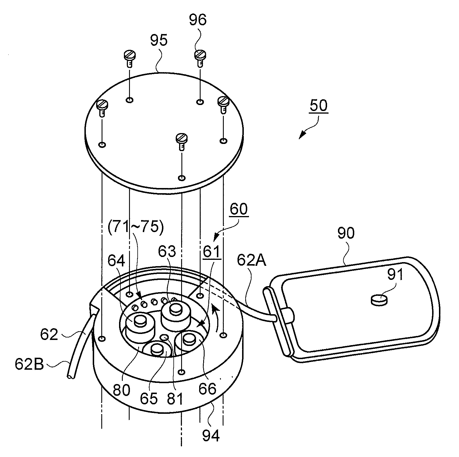
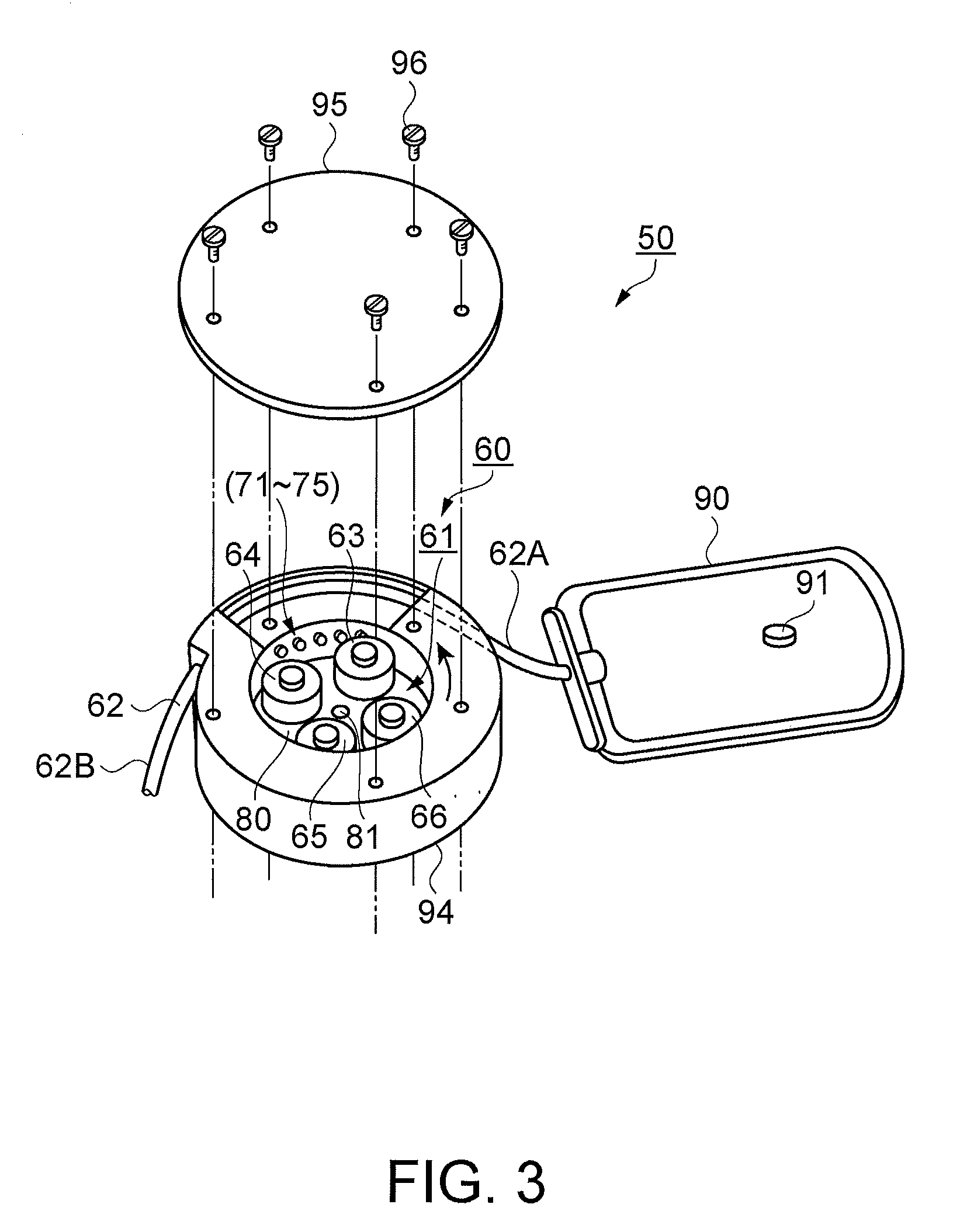
[0275]An identification sticker, on which the barcode or QR code is displayed as a display portion expressing the identification data, is stuck in a vicinity of a joint surface (the bottom of the casing 94) of the micro pump module 60 of the embodiment with the communication device 30. Then, a reader which reads the identification data is furnished in a vicinity of a joint surface of the communication device 30 with the micro pump module 60.

[0276]On mounting the fluid conveyance device 50 on the communication device 30, the connection terminals 97 and 98 provided on the commun...


PUM


Abstract

A fluid conveyance system includes: a fluid conveyance device including a micro pump module which compresses a flexible tube communicating with a fluid containing receptacle and discharges a fluid, a memory device furnished on the micro pump module which stores individual identification data of the micro pump module, and a power source; a discharge data processing device which stores basic data for driving the fluid conveyance device; and a communication device having a communication unit which interconnects the fluid conveyance device and the discharge data processing device, wherein the discharge data processing device inputs discharge data, for discharging a desired discharge amount of a fluid, calculated from the identification data and the basic data read via the communication device, into the memory device via the communication device, and the fluid conveyance device is driven based on the discharge data.

Description

BACKGROUND[0001]1. Technical Field[0002]The present invention relates to a fluid conveyance system which, including a miniature fluid conveyance device, a discharge data processing device, and a communication device, individually recognizes and drives the fluid conveyance device, and to the fluid conveyance device.[0003]2. Related Art[0004]In recent years, a use in medical treatment of a miniature pump for continuously administering a minute amount of chemical liquid, in a form of a gentle stream, to a patient is being researched.[0005]For example, as a miniature peristaltic pump device suitable for mounting in a human body for injecting an aqueous chemical liquid or the like at a low speed and continuously, there is a miniature peristaltic pump device which, a pump rotor being attached to a shaft, a plurality of rollers being disposed on the rotor, in an evenly dispersed condition on a periphery of the shaft, the rollers carrying out a rotating motion while rolling along a flexible...

Claims


Application Information

Patent Timeline
Patent Type & Authority Applications(United States)
IPC IPC(8): A61M5/142F04B43/12F04B49/00
CPCA61M5/1413A61M5/14232A61M5/14276A61M5/172A61M2205/3523A61M2205/3569F04B49/065A61M2205/6018A61M2205/8206F04B43/0081F04B43/12F04B43/1253F04B49/00A61M2205/52
Inventor MIYAZAKI, HAJIMEKAWASUMI, KAZUO
Owner SEIKO EPSON CORP
Why Eureka
Try Eureka