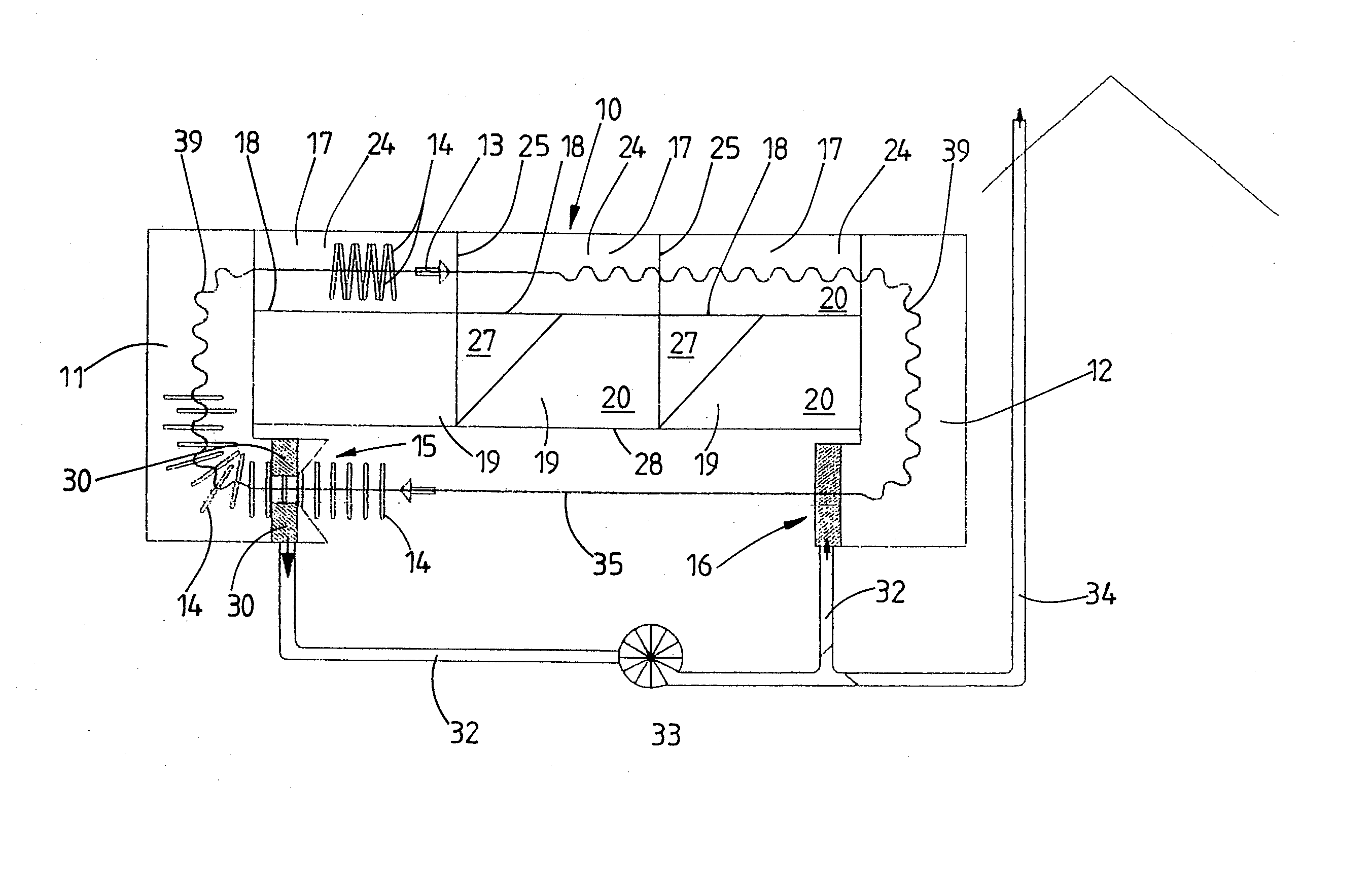
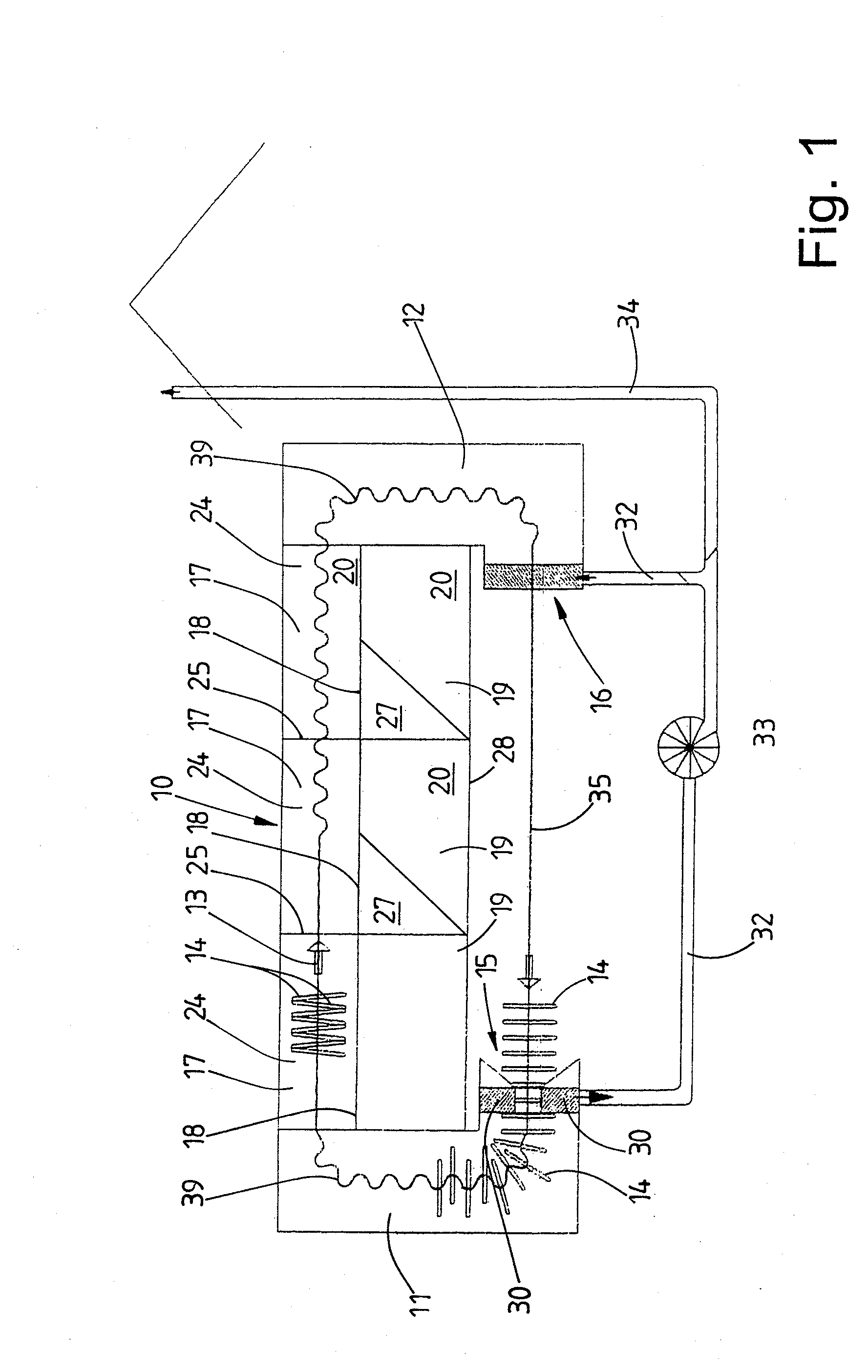
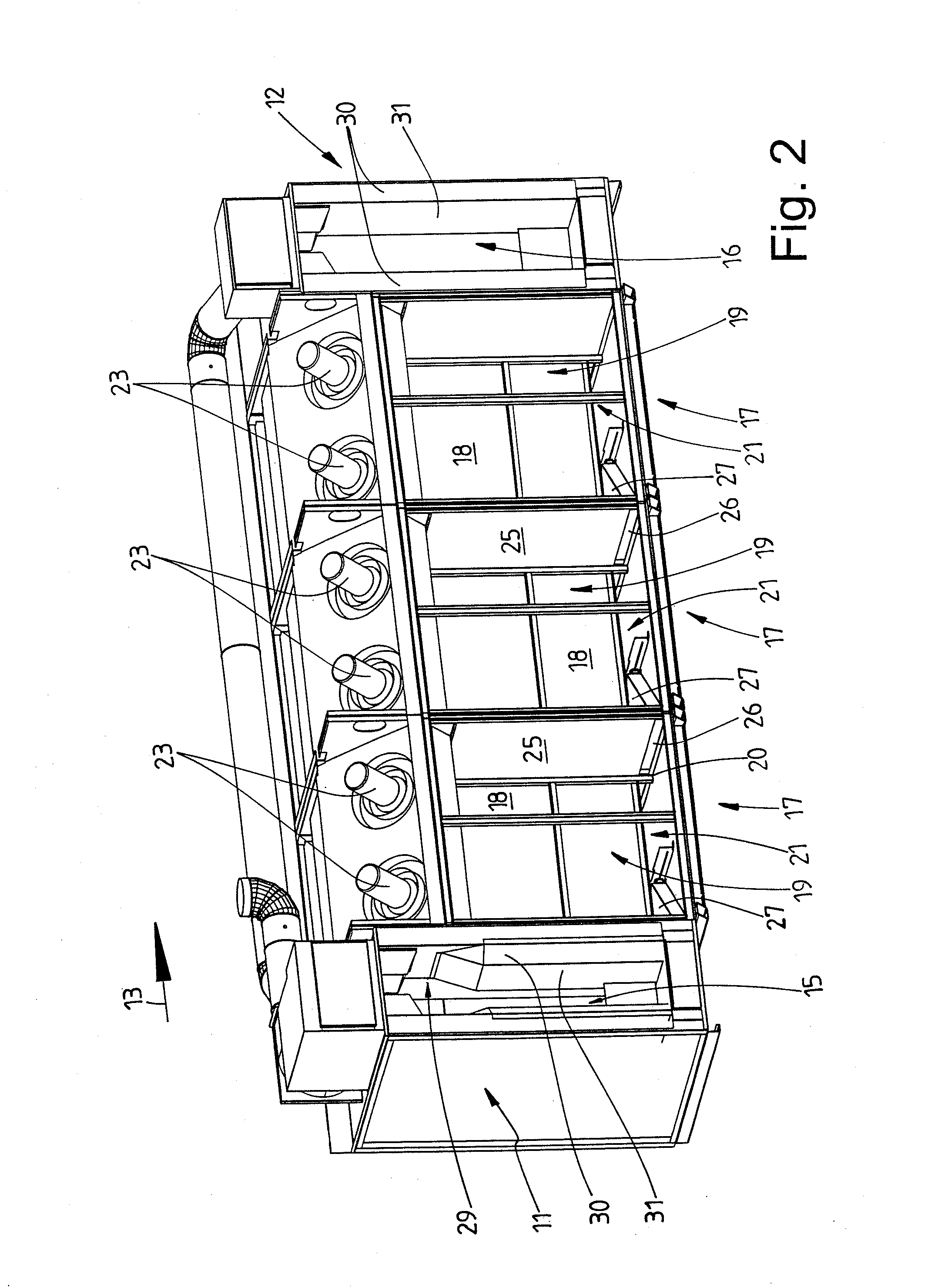
[0022] A tunnel finisher for achieving the object has the features of a tunnel finisher for smoothing articles of clothing, comprising (a) an admission chamber having an admission opening, a treatment chamber and a discharge chamber having a discharge opening, wherein, in the treatment chamber, (b) an air flow directed transversely with respect to a transporting direction of the articles of clothing through the treatment chamber, and (c) a means for producing an air flow assigned to the treatment chamber, the means for producing an air flow produces an air flow directed counter to the transporting direction of the articles of clothing through the treatment chamber. According thereto, it is provided according to the invention that the treatment chamber is assigned means for producing an air flow directed counter to the transporting direction of the articles of clothing through the treatment chamber, namely a counter air flow. The counter air flow leads to a particularly
intensive treatment of the articles of clothing in the finisher, above all to more effective
drying. In addition, moist air is transported to the start of the treatment chamber and from there to the admission chamber where the moist air can optionally be removed by suction. All this contributes to a more economical manner of operating the tunnel finisher.
[0023] The counter air flow is preferably produced by it being possible for at least one air supply opening which opens into the treatment chamber to be supplied with additional air from a region of the treatment chamber that is situated behind it. A
positive pressure is thus produced in the front region of the treatment chamber, as a result of which the air, in particular hot air, flows counter to the transporting direction of the articles of clothing through the treatment chamber in the direction of the start of the treatment chamber and to the admission chamber of the tunnel finisher.
[0024] In a preferred refinement of the invention, the treatment chamber is formed from a plurality of consecutive modules in the transporting direction of the articles of clothing through the tunnel finisher. The number of modules may be as desired. It fits in with the efficiency of the tunnel finisher. The modules are divided by vertical partitions running in the transporting direction into a treatment chamber section and an air guiding chamber situated next to it. By means of ventilators, air can be sucked into the air supply chamber from the bottom region of the particular treatment chamber section. In this case, it is provided according to the invention to suck in some air from the bottom region of the treatment chamber section of a module into the air guiding chamber of the same module and some air into the air supply chamber of the preceding module in the transporting direction. A spiral passage of the air through the treatment chamber of the tunnel finisher is thus produced, to be precise counter to the transporting direction. As a result, a counter air flow which flows through the entire treatment chamber counter to the transporting direction is produced. Since in the last module, as seen in the transporting direction, some of the air is conducted out of the bottom region of the treatment chamber section into the preceding module, there is an air deficit in the last module. This is compensated for by air from the discharge chamber. By contrast, there is an air excess in the first module. The excess air of the first module flows into the admission chamber. The counter air flow which is directed counter to the transporting direction also comes about by sucking up air from the discharge chamber and conducting air away into the admission chamber.
[0026] The admission and / or discharge chamber preferably has / have a length which goes beyond the width of the treatment chamber, preferably by at least the width of the admission and / or discharge chamber. By means of the relatively long admission chamber, effective heating of the articles of clothing or else
laundry is brought about. It is thus possible for the articles of clothing to already be heated to the cooling limit temperature of approximately 90° C. in the admission chamber. As soon as the articles of clothing reach the treatment chamber, the finishing operation can begin. The effect achieved by a relatively long discharge chamber is that the reevaporation zone is extended. Points of the articles of clothing, such as seams, hems or doubled widths of material, which are difficult to dry can thus be dried for longer. In addition, the temperature of the articles of clothing in the longer discharge chamber is lowered to a relatively great extent, and therefore they only have to be cooled a little, if at all, when they leave the tunnel finisher.
[0027] The object mentioned at the beginning is furthermore achieved by a tunnel finisher with the features of a tunnel finisher for smoothing articles of clothing, comprising an admission chamber having an admission opening, a treatment chamber and a discharge chamber having a discharge opening, wherein the articles of clothing are transported through the treatment chamber in a transporting direction, and wherein at least part of the width of the admission opening and / or of the discharge opening is smaller than the average width of the articles of clothing. This may also be a preferred development of the tunnel finisher described previously. According thereto, the width of the admission and / or discharge opening is smaller over at least part of its / their height than the average width of the items of clothing. The items of clothing are usually transported through the tunnel finisher in a manner oriented transversely with respect to the transporting direction. Accordingly, the admission and discharge openings are usually of a width which corresponds to the maximum width of the articles of clothing to be finished, and preferably somewhat larger. By contrast, the admission opening may also be somewhat smaller than the maximum width of the articles of clothing to be finished. As a result, the admission and discharge openings result in relatively low energy losses. In the case of the tunnel finisher according to the invention, the area of the admission and discharge openings is thus kept as small as possible. In addition, the articles of clothing are constricted in the region of the admission and discharge opening and, as a result, they close the openings for the most part, thus reducing the
air exchange at the admission and / or discharge opening, which results in lower energy losses in the tunnel finisher.
[0028] The width of the admission and discharge openings is preferably only reduced in a lower region of the articles of clothing to be transported through the tunnel finisher, which region hangs down from a transporting hanger. As a result, the rigid transporting hangers together with upper parts of the items of clothing can be transported in a transversely directed manner through the admission and discharge openings without impediment while those soft and flexible regions of the articles of clothing which are located below the transporting hangers are constricted in the narrower admission and discharge openings.
[0011] The tunnel finisher, in particular its treatment chamber, is preferably formed from a plurality of consecutive modules. The production of the counter air flow takes place by introducing at least some of the air produced in at least one module, in particular warm air, into the previous module in the transporting direction. This takes place in that, when some of the warm air is introduced into the previous module, a
positive pressure is produced in the same and increases from module to module counter to the transporting direction. This results in the production in the treatment chamber of a
spiral flow which extends through the treatment chamber counter to the transporting direction and brings about, in particular produces, the counter air flow in the treatment chamber. By the quantity of air which is conducted from the module in which it is produced into the previous module being changed, the differences in pressure in the consecutive modules can be changed and, accordingly, the flow velocity of the counter air flow increased or reduced.
[0030] In a preferred refinement of the apparatus, it is provided that the warm air sucked up at the suction openings of the admission openings is used in order to feed the blowing openings at the discharge opening of the discharge chamber. The warm air removed by suction at the admission opening is used in order, at the discharge opening, to form a warm air curtain which, at least for the most part, avoids cold
ambient air being sucked in.
[0031] A further tunnel finisher for achieving the object mentioned at the beginning, which may also be a development of the tunnel finishers described previously, has the features of a tunnel finisher for smoothing articles of clothing, comprising an admission chamber having an admission opening, a treatment chamber and a discharge chamber having a discharge opening, wherein the articles of clothing are transported through the treatment chamber in a transporting direction along a conveying
route, and wherein some regions of the conveying
route of the articles of clothing are increased. Said tunnel finisher is distinguished in that the conveying
route of the articles of clothing through the treatment zone is increased at least in the end region of the treatment zone. The treatment zone may be an end region of the treatment chamber or else the discharge chamber. Since the articles of clothing hanging on the transporting hanger are usually transported through the tunnel finisher by means of an encircling conveyor, the
residence period of the articles of clothing in each section of length of the tunnel finisher is inevitably the same. The
residence period of the articles of clothing can be increased by the conveying route, which is extended according to the invention, of the tunnel finisher which is assigned the extended conveying route. It is thereby possible, for example, to increase the period of reevaporation of the articles of clothing in the tunnel finisher although the conveying speed of the conveyor running continuously through the tunnel finisher corresponds, even in the reevaporation and / or
drying region, to that of the preceding regions of the tunnel finisher.
[0032] The extension of the conveying route in certain regions of the tunnel finisher is preferably brought about by a serpentine-like course of the conveying route in the regions concerned of the tunnel finisher.


