Light emitting diode (L.E.D.) lighting fixtures with emergency back-up and scotopic enhancement

a technology of light-emitting diodes and lighting fixtures, which is applied in the manufacture of electric discharge tubes/lamps, lighting and heating apparatuses with built-in power, etc., can solve the problems of multiple shadows, increased number of fatal shocks, and inability to completely handle the changes in luminance necessary for efficient visual function.

Inactive Publication Date: 2008-02-14
BOLTA CHARLES
View PDF7 Cites 63 Cited by
  • Summary
  • Abstract
  • Description
  • Claims
  • Application Information

AI Technical Summary

Benefits of technology

[0012] The L.E.D. lighting fixture can also be part of an emergency lighting system that can withstand extreme stresses, be reliable, and have a long life. It has been demonstrated that it is critical to an emergency lighting system to include the use of L.E.D.'s made with a scotopically rich primary color. Increasing the eye's ability to respond to low levels of light could be critical to a person's ability to react in an emergency situation. Also, the primary scotopic color of L.E.D.'s in this preferred system prepares the eye to respond and adapt quickly to changes in footcandles of light when the emergency lights come on.
[0013] L.E.D.'s typically have a lower lumen per watt output than fluorescent or incandescent lamps. Using L.E.D.'s with a higher scotopic output increases perceived light, visual acuity and response of the eye under typically low lumen output L.E.D.'s
[0014] The designs of the present application address a number of problems including: mercury on nuclear vessels, breakage of normal light filaments during explosions or shock, the presence of ultraviolet light that degrades plastics over time, maintenance issues, interrupted light source with unreliable battery back-up, and high energy consumption, all of which are above and beyond normal fluorescent lighting used in Navy Subs and surface ships and any application where normal lighting and / or combined with emergency lighting highly resistant to explosion or shock is needed. Another problem we have addressed with this design is multiple shadows which are more pronounced with multiple L.E.D.s and stronger lumen output L.E.D.s. A novel shadow reduction lens with sub-lens helps reduce the shadowing problem and also helps keeps up the lumen output of the fixture.
[0015] The use of scotopic / photopic blends and ratios help maximize eye to lumen response and photochemical and transient adaptation to darkness in emergency situations. The scotopic range of light can be adjusted to reduce melatonin levels depending on desired effects of performance of occupants of an environment. For example the 3rd shift in a motor room or industrial application where a higher ratio, for example 50% blue light L.E.D.s between 420-490 nm and 50% white light L.E.D.s, could be increased or adjusted to lower melatonin levels and / or then the light ratio could be put back to any ratio of white light L.E.D.s therefore keeping 3rd shift workers awake longer, depending on building design features including ceiling height and reflectivity of surfaces.
[0017] The L.E.D. lighting fixture addresses a problem with temporary lighting used for example in construction or in mines where light fixtures are strung up in an area and not securely fastened and fixtures have been known to fall. There have been a number of instances of fatal shock that have occurred with high voltage lighting. The new L.E.D. lighting fixture 10 can be run on either high or low voltage therefore reducing or eliminating shock hazard. Also, the internal metal framing structure, which holds the L.E.D.'s, has special anodized coatings to make them non-conductive further insulating people from shock hazard.

Problems solved by technology

Under these conditions, and in situations associated with exteriors, neural adaptation will not be completely able to handle the changes in luminance necessary for efficient visual function.
Transient adaptation is usually insignificant in interiors, but can be a problem in brightly lighted interiors or exteriors where photopigment bleaching has taken place.
Another problem we have addressed with this design is multiple shadows which are more pronounced with multiple L.E.D.s and stronger lumen output L.E.D.s.
There have been a number of instances of fatal shock that have occurred with high voltage lighting.

Method used


Image

  • Light emitting diode (L.E.D.) lighting fixtures with emergency back-up and scotopic enhancement
  • Light emitting diode (L.E.D.) lighting fixtures with emergency back-up and scotopic enhancement
  • Light emitting diode (L.E.D.) lighting fixtures with emergency back-up and scotopic enhancement

Examples


Embodiment Construction

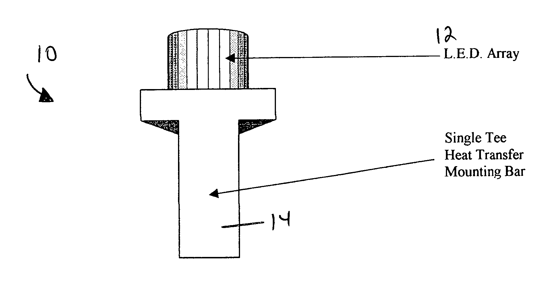
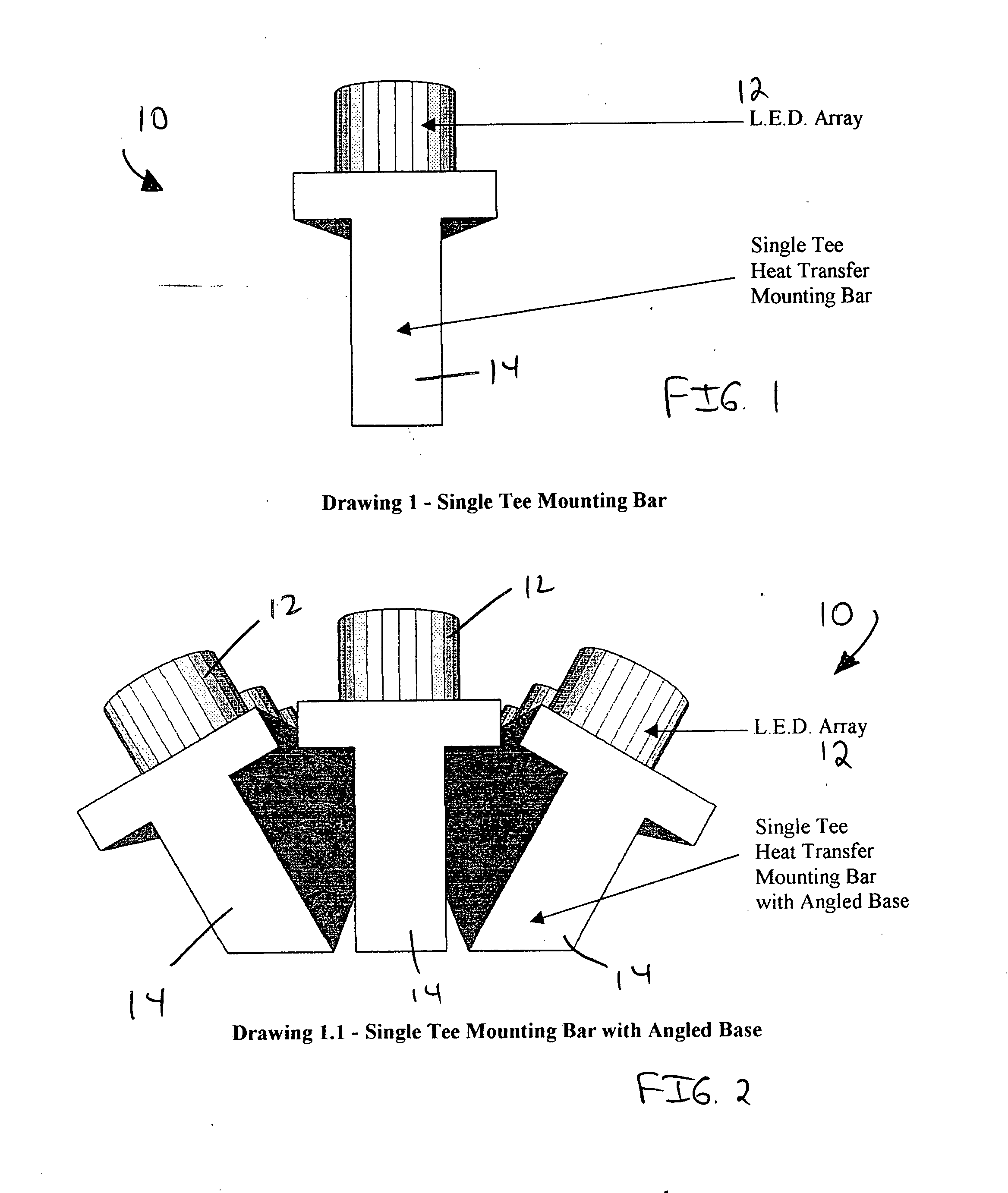
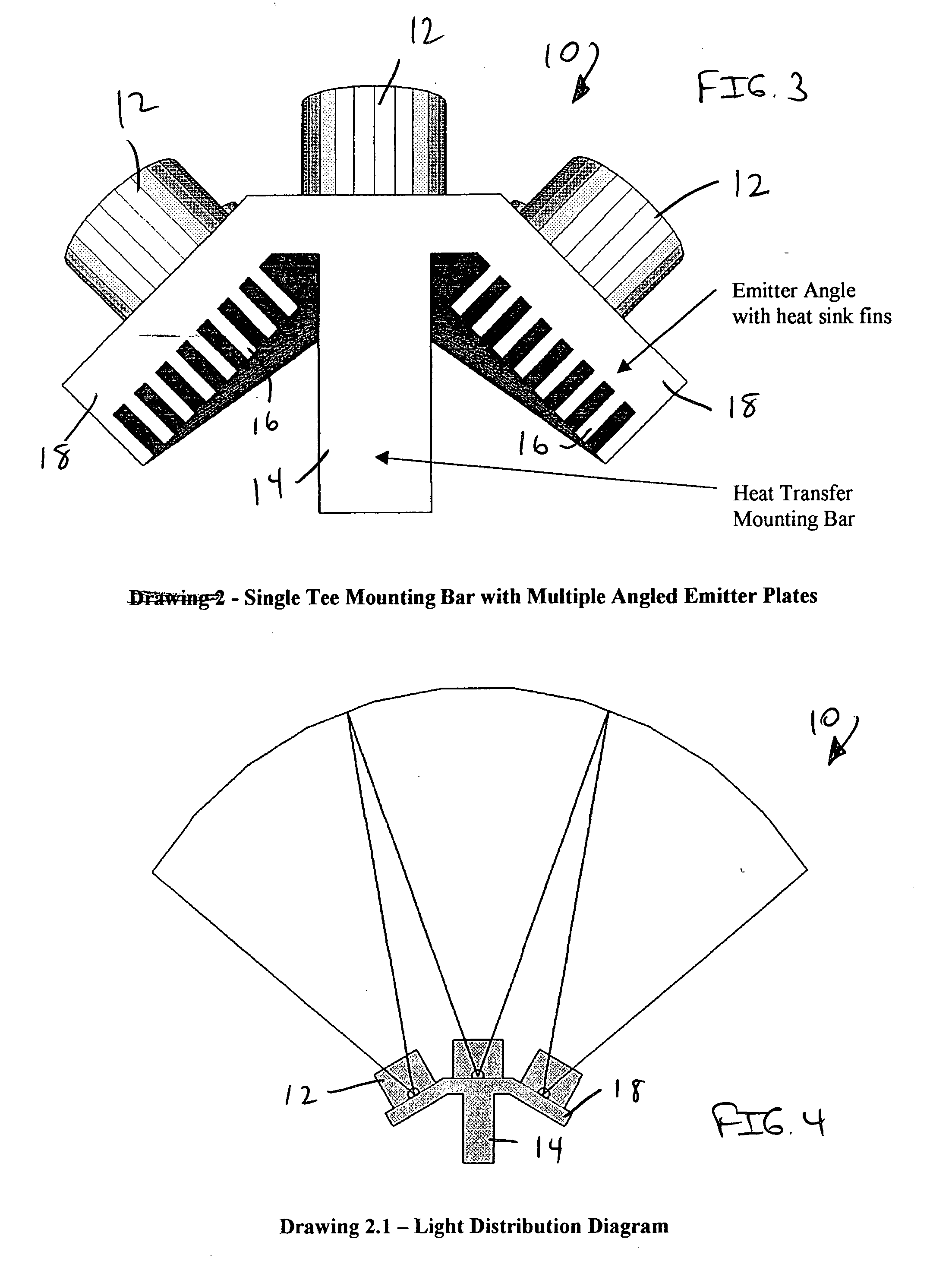
[0042] As illustrated in FIGS. 1-24, the present invention is an L.E.D. (Light Emitting Diode) lighting fixture, indicated generally at 10, for use as an alternative light source capable of replacing typical fluorescent and incandescent fixtures. L.E.D.'s inherently emit either a direct highly concentrated beam spread or a diffuse light with extremely low lumens. The L.E.D. array lighting fixture 10 of the present invention is configured so that the lighting fixture 10 emits a dispersed wide beam spread similar to the output of existing fluorescent and incandescent fixtures.

[0043] The L.E.D. lighting fixture 10 of the present invention configures arrays of L.E.D.'s 12 for spreading light evenly and more closely matching the footcandle output and footcandle spread for a full 180-degrees or a modified beam spread as required for each application. The L.E.D. lighting fixture 10 of the present invention can be used as temporary or permanent lighting.

[0044] The use of scotopic / photopic...


PUM


Abstract

An L.E.D. lighting fixture is provided. The lighting fixture comprises at least one heat transfer mounting bar, at least one emitter plate secured to the mounting bar, an array of L.E.D. lights secured to each emitter plate, and a diffusion lens mounted over the L.E.D. array. A method for providing light is also provided.

Description

[0001] The present application is a continuation-in-part and claims priority of pending patent application Ser. No. 10 / 732,105, filed on Dec. 10, 2003, and pending provisional patent application Ser. No. 60 / 432,429, filed on Dec. 11, 2002, both entitled “Light Emitting Diode (L.E.D.) Lighting Fixtures with Emergency Back-Up and Scotopic Enhancement”.BACKGROUND OF THE INVENTION [0002] 1. Field of the Invention [0003] This invention relates generally to light emitting diode lighting fixtures and, more particularly, the invention relates to light emitting diode lighting fixtures with emergency back-up and scotopic enhancement. [0004] 2. Description of the Prior Art [0005] Although receptive field sizes account for some of the differences in visual sensitivity across the retina, the sensitivity at a given retinal location can also vary. The human eye can process information over an enormous range of luminance (about twelve (12) log units). The visual system changes its sensitivity to li...

Claims


Application Information

Patent Timeline
Patent Type & Authority Applications(United States)
IPC IPC(8): F21V29/00F21K99/00F21S9/02F21V29/02
CPCF21K9/00F21S9/022F21V5/002F21V5/02F21V19/001F21V29/004F21V29/777F21Y2101/02H05B33/0803F21S4/008F21K9/137F21V29/75F21V29/76F21V29/02F21V9/08F21S4/28F21K9/233F21K9/69F21Y2115/10F21V9/30F21V9/40F21V29/71
Inventor BOLTA, CHARLES
Owner BOLTA CHARLES
Why Eureka
Try Eureka