
Audio output device and method for calculating parameters

a technology of audio output device and parameter calculation, which is applied in the direction of transducer details, electrical transducers, automatic tone/bandwidth control, etc., can solve the problems of unsuitability of scheme (1), unsuitability of scheme (2), and inability to advance measurement in many cases, so as to achieve easy use of various audio output devices, low cost, and simple arithmetic operation

Inactive Publication Date: 2008-02-14
SONY CORP
View PDF1 Cites 21 Cited by
  • Summary
  • Abstract
  • Description
  • Claims
  • Application Information

AI Technical Summary

Benefits of technology

[0012] There is a need for the present invention to make an improvement to the process of calculating parameters for frequency characteristic correction by a parametric equalizer, to thereby allow the parameter calculation through simple arithmetic operation.
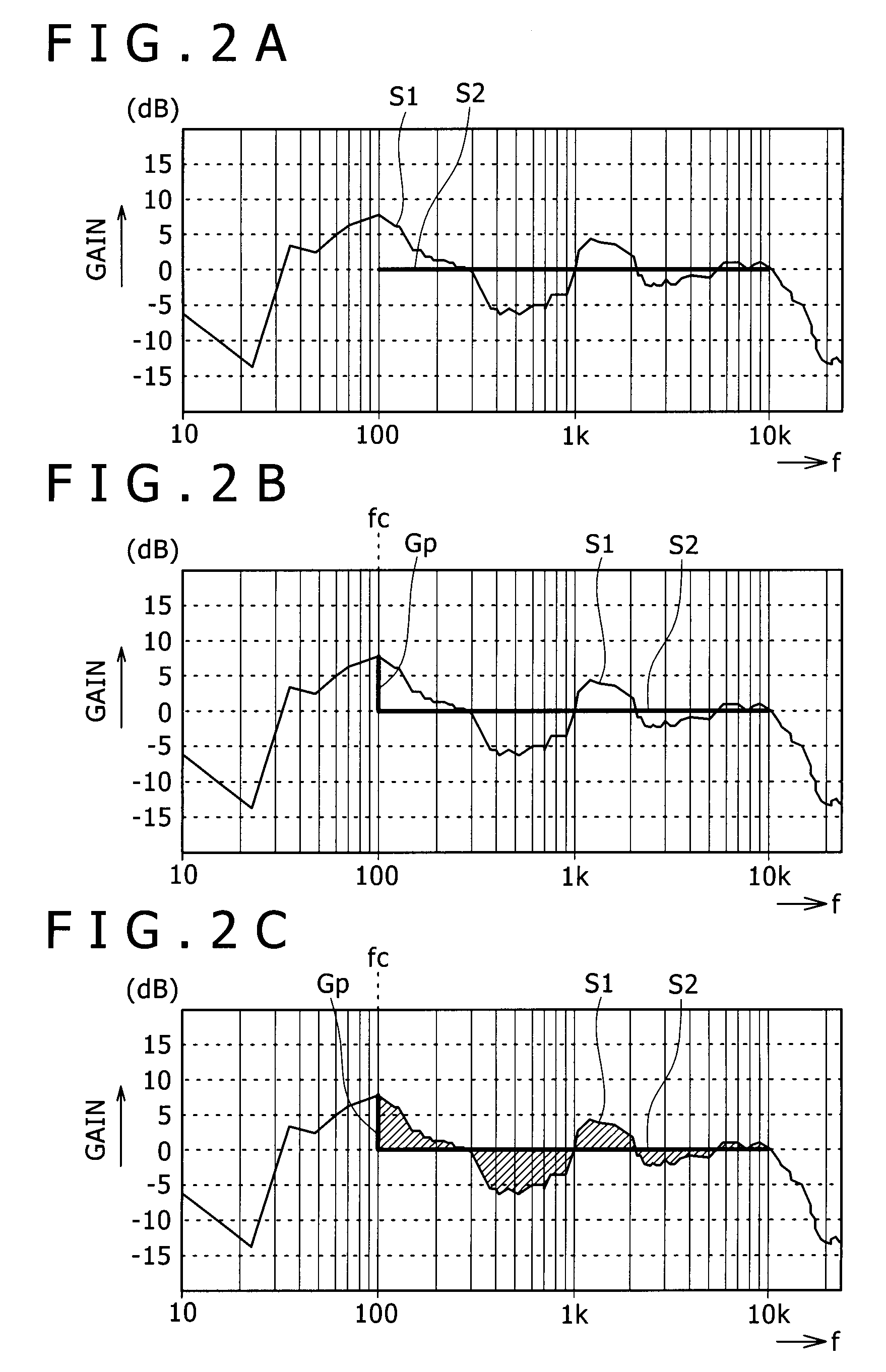
[0015] The embodiments of the present invention relate to an audio output device in which frequency characteristic analysis is carried out for a measurement signal (signal to be measured) collected through a microphone and encompassing the transfer characteristic of the space, and an equalizer corrects the frequency characteristic of an audio signal output from a speaker (audio signal to reach the position of the microphone from the speaker) depending on the analysis result so that the frequency characteristic may be brought close to a target frequency characteristic. In particular, the embodiments can employ improvements relating to the way of holding gain sequences as equalizer characteristics and the arithmetic method for determining proper parameters. This allows the optimum equalizer parameters for the correcting to the target frequency characteristic to be calculated only through very simple arithmetic operation (i.e., integer-type sum-of-products operation).
[0023] This scheme offers an advantage that the parameters of a parametric equalizer for multiband can be calculated only through addition and subtraction of integer-type variables. This calculation can be executed even by a low-speed and low-function arithmetic unit (e.g. a cheap microcomputer or digital signal processor (DSP)), and hence can be easily employed in various audio output devices at low costs.
[0024] A correction characteristic table holds gain sequences as equalizer correction characteristics corresponding to combinations of a center frequency, gain, and sharpness. A correction characteristic of a parametric equalizer shows the same curve on a logarithmic scale irrespective of the center frequency, and is symmetric on a logarithmic scale. Furthermore, frequency points having equal intervals on a logarithmic scale can be employed as the respective points of a gain sequence as a correction characteristic. Therefore, gain sequences corresponding to various combinations of a center frequency, gain, and sharpness can be obtained through simple arithmetic operation on a certain basic gain sequence. Consequently, the necessary information amount as the correction characteristic table can be significantly reduced. That is, the burden of the correction characteristic table used for parameter calculation is also significantly reduced.

Problems solved by technology

Therefore, the scheme (1) is unsuitable for the situation where resources for the correction processing are limited and the situation where advanced measurement may be impossible.
Therefore, the scheme (2) is also unsuitable in many cases.
Specifically, in processing for determining parameters (center frequency, gain, and sharpness (Q value)) of a parametric equalizer, the processing burden and memory burden for calculation of the parameters are very heavy because (floating) decimal point arithmetic and complex arithmetic with the trigonometric function are used, and a table with a very large size is necessary for the calculation.
The kind of hardware that can execute such arithmetic is limited.

Method used


Image

  • Audio output device and method for calculating parameters
  • Audio output device and method for calculating parameters
  • Audio output device and method for calculating parameters

Examples


Embodiment Construction

[0043] An embodiment of the present invention will be described below in the following order: [0044] [1. Configuration of Audio Reproduction Device][0045] [2. Setting of Parameters of Parametric Equalizer][0046] [3. Reduction in Information Amount of Correction Characteristic Table]

[1. Configuration of Audio Reproduction Device]

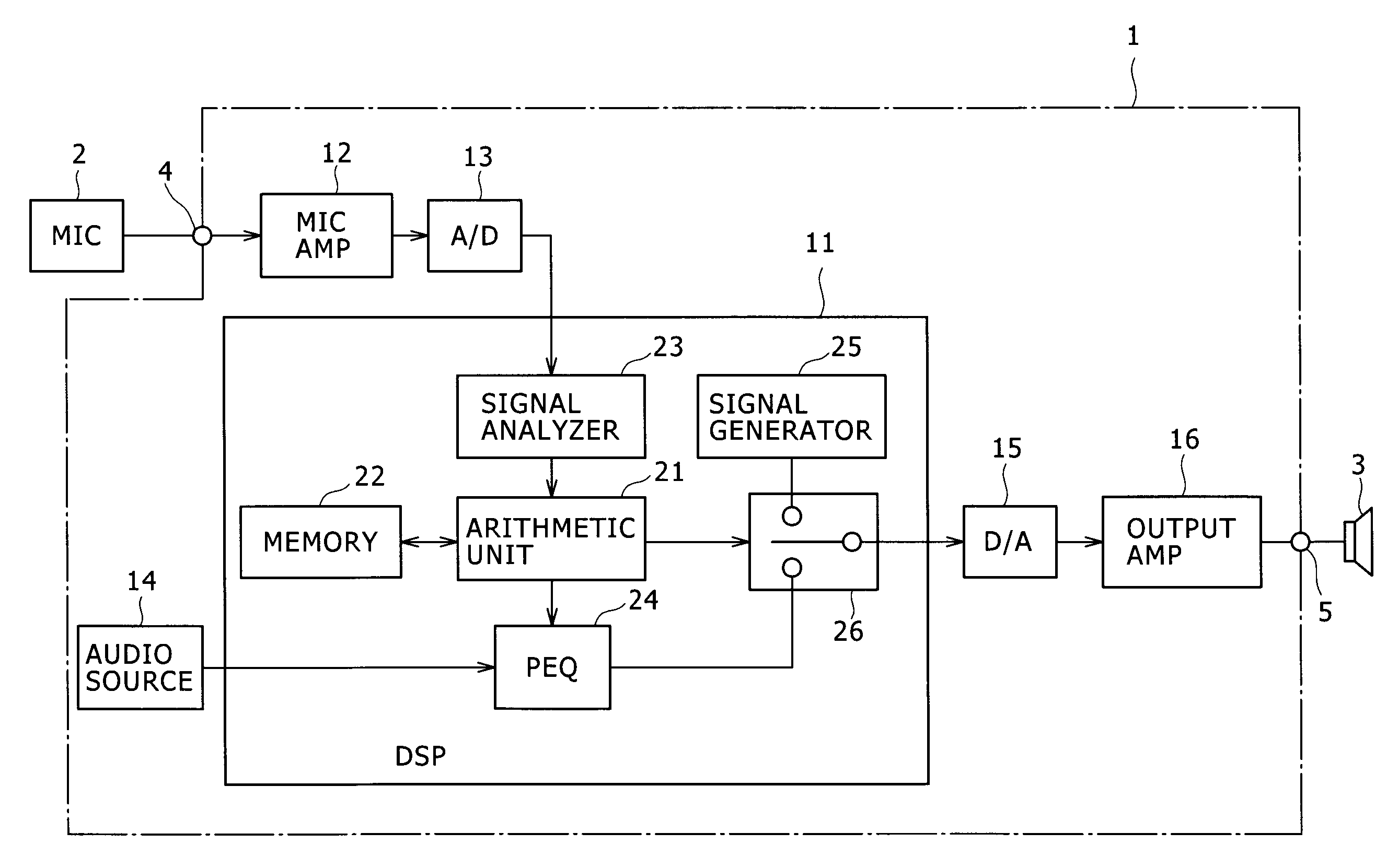
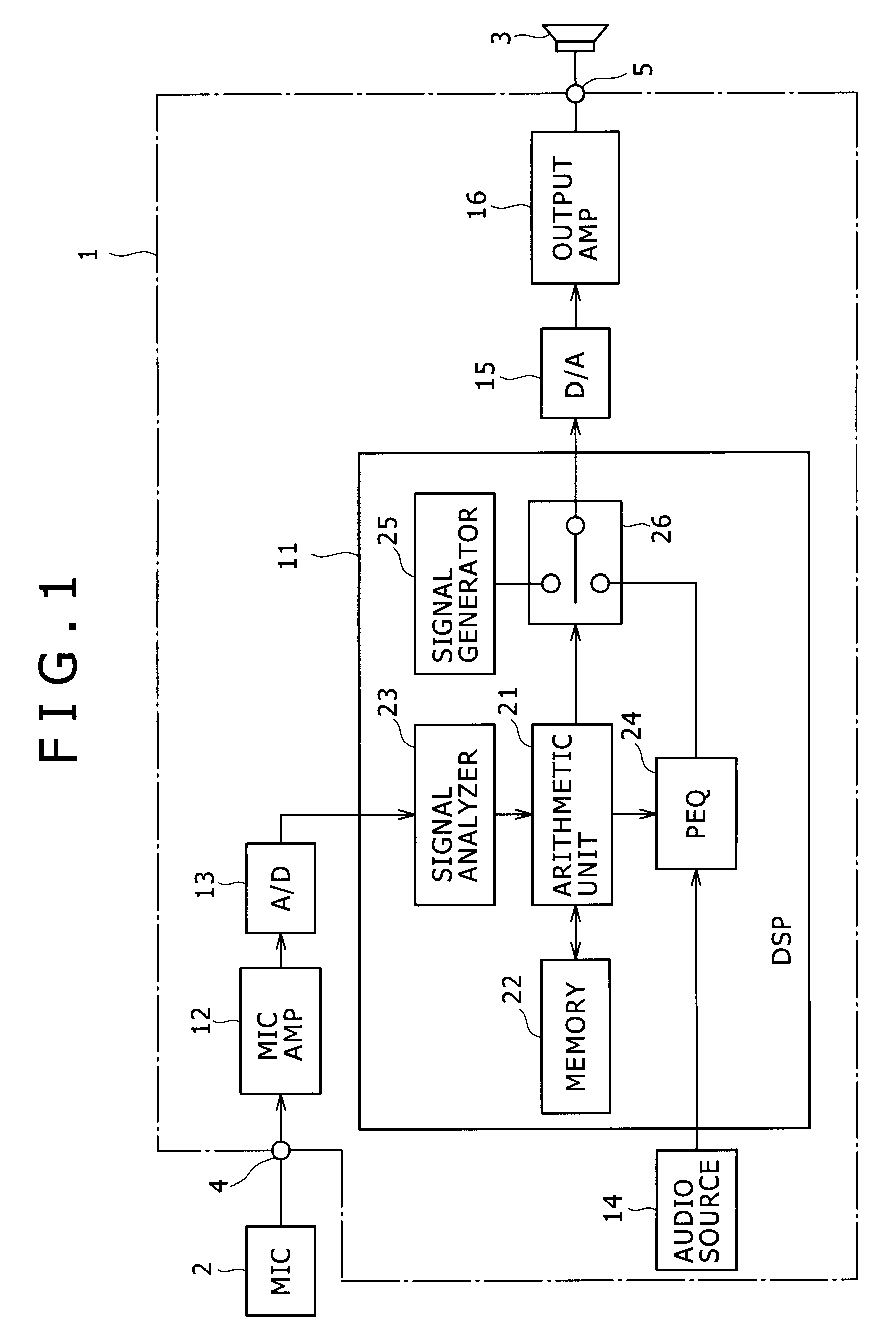
[0047]FIG. 1 shows the configuration of an audio reproduction device that is one form of an audio output device according to an embodiment of the present invention. The audio reproduction device is realized as e.g. a vehicle or home audio reproduction device.

[0048] An audio reproduction device 1 outputs from a speaker 3 connected thereto an audio signal produced by an audio source 14. As the audio source 14, e.g. a reproduction device that reproduces an audio signal from an optical disc such as a compact disc (CD) or digital versatile disc (DVD) or a tuner device that receives / demodulates radio broadcasting to output an audio signal would be available. Alte...


PUM


Abstract

Disclosed herein is an audio output device including: an equalizer configured to execute frequency characteristic correction processing for an audio signal from an audio source; an output part configured to supply an audio signal processed by the equalizer to a speaker for audio output from the speaker; a signal analyzer configured to analyze a frequency characteristic of an input audio signal to thereby obtain a gain of each of sample points on a frequency axis; and an arithmetic unit configured to control parameters of the equalizer, the arithmetic unit extracting sample points having substantially equal intervals on a logarithmic-scale frequency axis from sample points of which gains have been obtained by the signal analyzer, the arithmetic unit calculating parameters of the equalizer by using differences between gains of the extracted sample points and gains at frequencies corresponding to the extracted sample points on a target frequency characteristic.

Description

CROSS REFERENCES TO RELATED APPLICATIONS [0001] The present invention contains subject matter related to Japanese Patent Application JP 2006-112936 filed in the Japan Patent Office on Apr. 17, 2006, the entire contents of which being incorporated herein by reference. BACKGROUND OF THE INVENTION [0002] 1. Field of the Invention [0003] The present invention relates to an audio output device that includes an equalizer for correcting a frequency characteristic, and to a method for calculating parameters of an equalizer. [0004] 2. Description of the Related Art [0005] As existing general schemes for correcting a transfer characteristic from a measured frequency characteristic to a target frequency characteristic, the following correction schemes are available: (1) a correction scheme employing an FIR filter based on impulse response measurement, (2) a correction scheme employing a graphic equalizer based on gain characteristic measurement (or impulse response measurement), and (3) a corr...

Claims


Application Information

Patent Timeline
Patent Type & Authority Applications(United States)
IPC IPC(8): H03G5/16
CPCH03G5/165H04S7/307H04S7/301
Inventor KINO, YASUYUKISAWASHI, TOKIHIKO
Owner SONY CORP
Learn More