Fuel Cell System And Method For Driving Same

a fuel cell and system technology, applied in the direction of fuel cells, solid electrolyte fuel cells, fuel cells, etc., can solve the problems of affecting the overall power generation efficiency of the system, especially high possible adverse effects, etc., and achieve the effect of reducing the size of the drive means and high power generation efficiency

Active Publication Date: 2008-02-14
TOYOTA JIDOSHA KK
View PDF7 Cites 2 Cited by
  • Summary
  • Abstract
  • Description
  • Claims
  • Application Information

AI Technical Summary

Benefits of technology

[0007]It is an object of the present invention to provide a fuel cell system that has a high power generation efficiency and allows the drive means to be reduced in size.
[0011]In accordance with the present invention, the drive load of the drive means can be adequately regulated by using the pressure of the fuel gas supply source to vary the pressure of the circulation route according to the required gas quantity of the fuel cell and to regulate the gas density in the circulation route. In particular, when the required gas quantity increases, the gas density in the circulation route can be increased by raising the pressure in the circulation route, and an excess increase in the drive load of the drive means can be prevented, thereby making it possible to reduce the drive means in size.
[0014]In accordance with the present invention, at least within a range where the required gas quantity is higher than a standard value, the pressure regulation quantity of the pressure regulating means is varied correspondingly to a variation of the required gas quantity. With such a structure, because the quantity of fuel is regulated by pressure variations of the fuel gas in a range with a high required gas quantity, the drive quantity with the drive means can be relatively reduced, and the power consumption of the drive means, which tends to increase remarkably when the load is high, can be reduced.
[0016]Furthermore, in accordance with the present invention, in a region in which the required gas quantity is higher than the standard value, the variation rate of the drive quantity of the drive means is preferably reduced with respect to a region in which the required gas quantity is lower than the standard value. With such a feature, because the variation rate of the drive quantity of the drive means in a region with a high required gas quantity is lowered, the drive quantity provided by the drive means drops and power consumption of the drive means that tends to increase significantly when the load is high can be decreased.
[0018]In accordance with the present invention, in a region in which the required gas quantity is lower than the standard value, the pressure regulation quantity of the pressure regulating means is preferably maintained equal to or less than a constant value. In a region where the required gas quantity is low, the consumption of fuel gas is low, but if the pressure of the fuel gas in the circulation route increases in this region, the leak (cross leak) of the fuel gas to an air electrode of the fuel gas increases, and the power generation efficiency of the fuel cell decreases. With the aforementioned feature, in a region with a low level of power generation where the consumption of fuel gas is small, the pressure of the fuel gas is maintained equal to or less that a fixed value, thereby preventing the inconvenience of such fuel gas leak.
[0021]In accordance with the present invention, when the required gas quantity rises, the gas density inside the circulation route can be increased by increasing the pressure inside the circulation route, and the drive load of the drive means can be prevented from becoming too high. Therefore, the drive means can be reduced in size the power generation efficiency of the entire fuel cell system can be increased.

Problems solved by technology

However, in the above-described well-known methods, the regulation between the drive quantity of the drive means such as a hydrogen pump or a turbine and the pressure regulation quantity of the circulation route is not considered, and the possibility of adverse effects is especially high when the fuel supply quantity is varied only with the drive means.
Thus, in the drive means such as a pump, because the power consumption of the power source increases with the increase of fuel cell load, the total power generation efficiency of the system tends to degrade when the load is high.
Furthermore, if the fuel supply in a high-load mode of a fuel cell is considered to depend only on the circulation quantity control provided by the drive means, the drive means is required to withstand high-speed rotation and circulate a large amount of fuel gas.

Method used


Image

  • Fuel Cell System And Method For Driving Same
  • Fuel Cell System And Method For Driving Same
  • Fuel Cell System And Method For Driving Same

Examples


embodiment 1

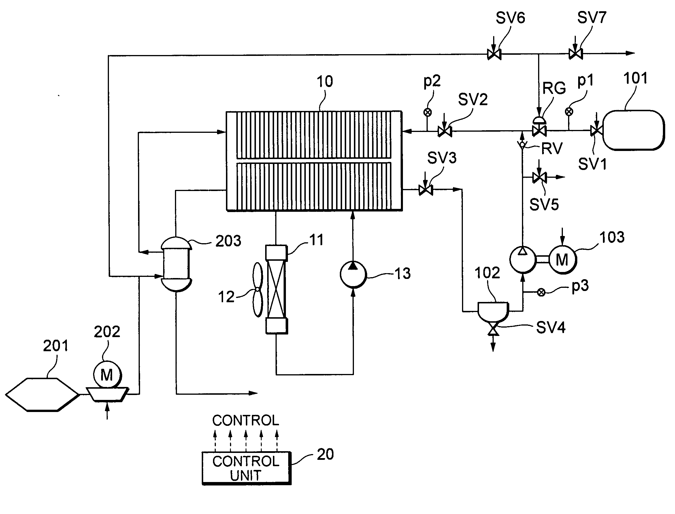
[0053]Specific embodiments of the present invention based on the above-described principle will be explained below. The embodiments of the present invention relate to the application of the control method in accordance with the present invention to fuel cell systems installed on mobile structures such as electric automobiles. FIG. 3 shows the present fuel cell system in its entirety. The below-described embodiment is merely one mode for implementing the present invention, and the present invention can be employed without being limited thereto.

[0054]As shown in FIG. 3, the fuel cell system comprises a system for supplying a hydrogen gas, which is a fuel gas, to a fuel cell stack 10, a system for supplying air, which is an oxygen source, and a system for cooling the fuel cell stack 10.

[0055]The fuel cell stack 10 has a stack structure having stacked therein a plurality of separators having channels for hydrogen gas, air, and cooling liquid and cells, each comprising a MEA (Membrane El...

embodiment 2

[0079]Embodiment 2 of the present invention relates a mode in which the system control of the fuel cell system identical to that of Embodiment 1 described hereinabove is changed depending on whether or not the required output is higher than a standard value. FIG. 9 shows a flowchart explaining the operation of Embodiment 2.

[0080]First, the control unit 20 computes the generated power Pr required for the fuel cell stack 10 based on the load quantity required for the fuel cell system, in the same manner as in Embodiment 1 (S21).

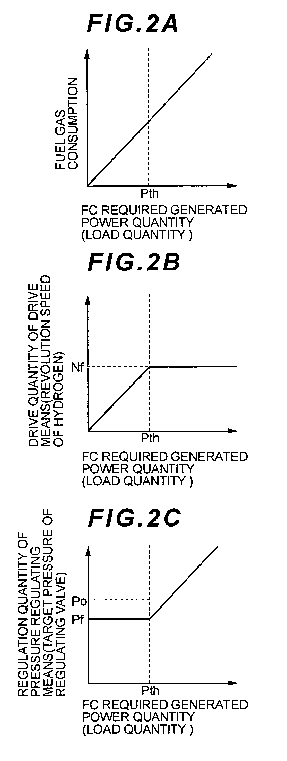
[0081]The control unit 20 then compares the required generated power Pr with a standard value Pth shown in FIG. 2 (S22). When the required generated power Pr is less than the standard value Pth, the hydrogen pump 103 does not increase significantly the consumption of power in response to load fluctuations. Accordingly, the control unit 20 fixes the target pressure Prg of the regulating valve RG and maintains it at an appropriate pressure Pf attained when the re...

embodiment 3

[0090]Embodiment 3 of the present invention relates to a modification example of a method for controlling the target pressure Prg of the regulating valve RG and the revolution speed Np of the hydrogen pump with the control unit in the fuel cell system control method identical to that of Embodiment 2 described hereinabove.

[0091]In Embodiment 3, when the required generated power Pr that is required for the fuel cell and the consumed quantity of the fuel gas correspond to each other as shown in FIG. 10A, the revolution speed of the hydrogen pump 103 is varied according to the characteristic such as shown in FIG. 10B and the target pressure of the regulating valve RG is varied according to the characteristic such as shown in FIG. 10C. In particular, in Embodiment 1, when the required generated power Pr was equal to or higher than the standard value Pth, the revolution speed of the hydrogen pump was set to a fixed value Nf. A specific feature of Embodiment 2 is that in this case the revo...


PUM

PropertyMeasurementUnit
pressureaaaaaaaaaa
poweraaaaaaaaaa
revolution speedaaaaaaaaaa

Abstract

A fuel system with a high power generation efficiency in which drive means can be reduced in size. The fuel cell system of the present invention is equipped with a fuel cell (FC) for generating power by circulating a fuel gas and comprises a circulation route (R) for circulating the fuel gas, drive means (PM) provided in the circulation route (R) and serving to circulate the fuel gas, and pressure regulating means (RG) for regulating the pressure of the fuel gas in the circulatory route (R). A drive characteristic of the drive means (PM) is determined based on the generated power required for the fuel cell, and the pressure regulation quantity of the pressure regulating means (RG) is determined to make up the deficiency of the drive quantity based on the determined drive characteristic of the drive means (PM).

Description

TECHNICAL FIELD[0001]The present invention relates to a fuel cell system, and more particularly to the improvement of a control method for reducing power consumption required to drive a fuel cell system when a load is high.BACKGROUND ART[0002]In fuel cell systems generating power by circulating a hydrogen gas, which is a fuel gas, in a fuel cell, an air supply pressure is controlled according to a power generation quantity of the fuel cell, that is, to load fluctuations, and the amount of consumed hydrogen gas is increased or decreased by changing the rotation speed of a hydrogen pump that causes forced circulation of the hydrogen gas.[0003]For example, Japanese Patent Application Laid-open No. 2003-68334 discloses a method by which the air pressurized in a compressor is introduced into a fuel gas pressure regulating valve and the difference in pressure between the poles of a fuel cell is regulated to be maintained within the prescribed range. The fuel gas is supplied with a hydroge...

Claims


Application Information

Patent Timeline
Patent Type & Authority Applications(United States)
IPC IPC(8): H01M8/04H01M8/10
CPCH01M8/04007H01M8/04097H01M8/04388Y02E60/50H01M8/04432H01M8/04753H01M8/0494H01M8/04402H01M8/04
Inventor YOSHIDA, NAOHIRO
Owner TOYOTA JIDOSHA KK
Why Eureka
Try Eureka