Radially staged RQL combustor with tangential fuel premixers

a tangential fuel premixer and combustor technology, applied in the field of rql combustors, can solve the problems of combustor flame extinction, increase in cost, and increase in hardware control methods and maintenance, and achieve the effects of reducing cost, improving durability, and low emission

Active Publication Date: 2008-02-21
TEETS JOSEPH MICHAEL MR
View PDF34 Cites 58 Cited by
  • Summary
  • Abstract
  • Description
  • Claims
  • Application Information

AI Technical Summary

Benefits of technology

[0009]In view of the foregoing disadvantages inherent in the known types of RQL combustors now present in the prior art, the present invention provides a new radially staged RQL combustor with tangential fuel premixers construction wherein the same can be utilized for providing a internal combustion energy device for a gas turbine engine to yield low emission, reduced cost, improved durability, mulifuel use including low BTU gas—bio fuels, good flame

Problems solved by technology

The main challenge with a combustor is controlling combustion flame temperature which by most part dictates emissions species levels of NOx (oxides of nitrogen, NO+NO2), CO (carbon monoxide) and UHC (unburned hydrocarbons).
To attain this approximate narrow band of flame temperatures, variable geometry means to the air supply could be incorporated but would add complexity in hardware control methods and maintenance yielding an increase of cost.
U.S. Pat. Nos. 5,894,720 and 5,966,926 LPP type combustors offer low emission at high end power level and incorporates staged premix fuel/air nozzles to assist in the reduction of emission at off design power or reduced power requirements and aide in the combustion flame stability, but too lean of a F/A ratio would cause combustor flame extinction.
Whittle in early years of gas turbines ˜1936 attempted to use fuel delivery in

Method used


Image

  • Radially staged RQL combustor with tangential fuel premixers
  • Radially staged RQL combustor with tangential fuel premixers
  • Radially staged RQL combustor with tangential fuel premixers

Examples


Embodiment Construction

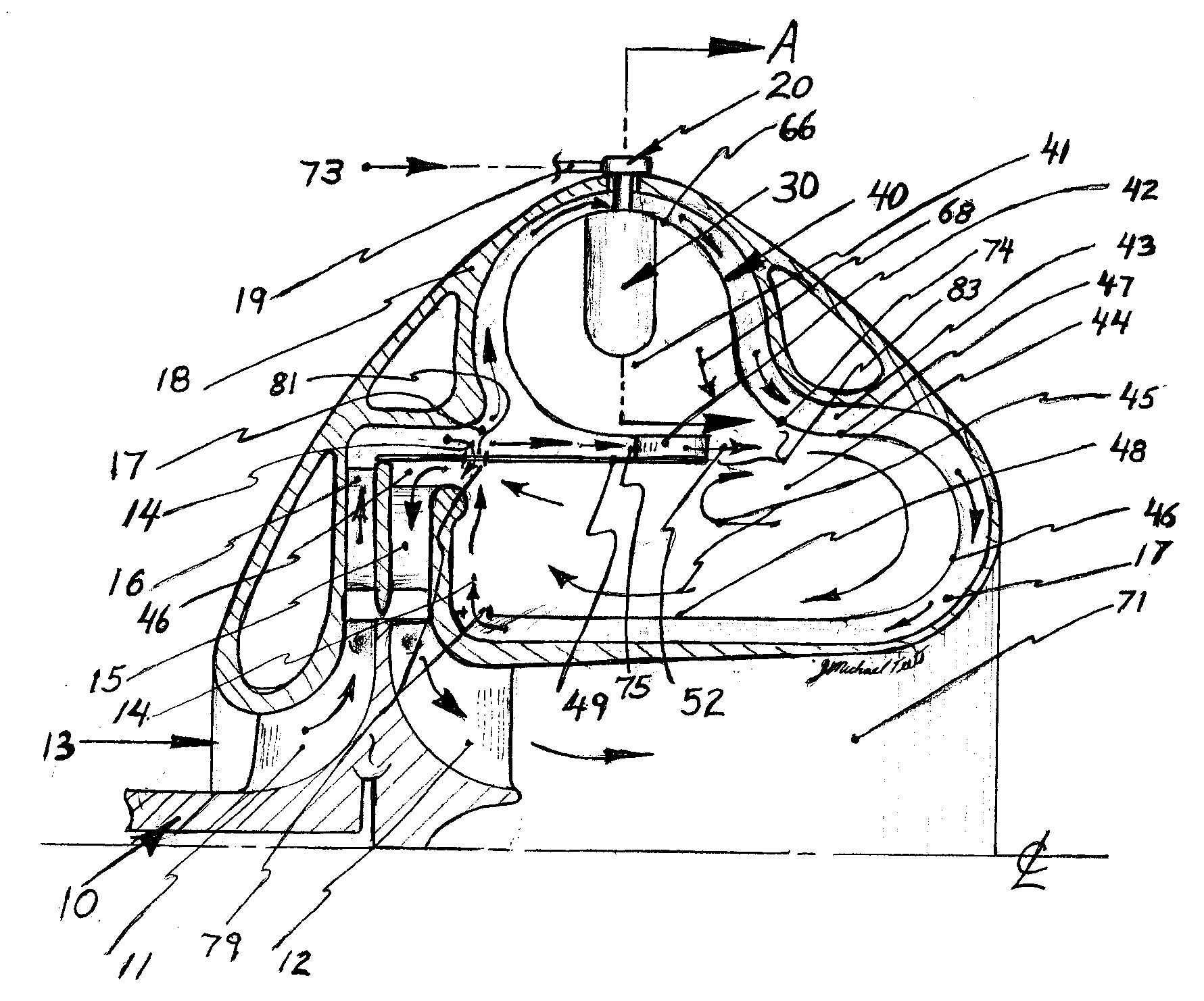
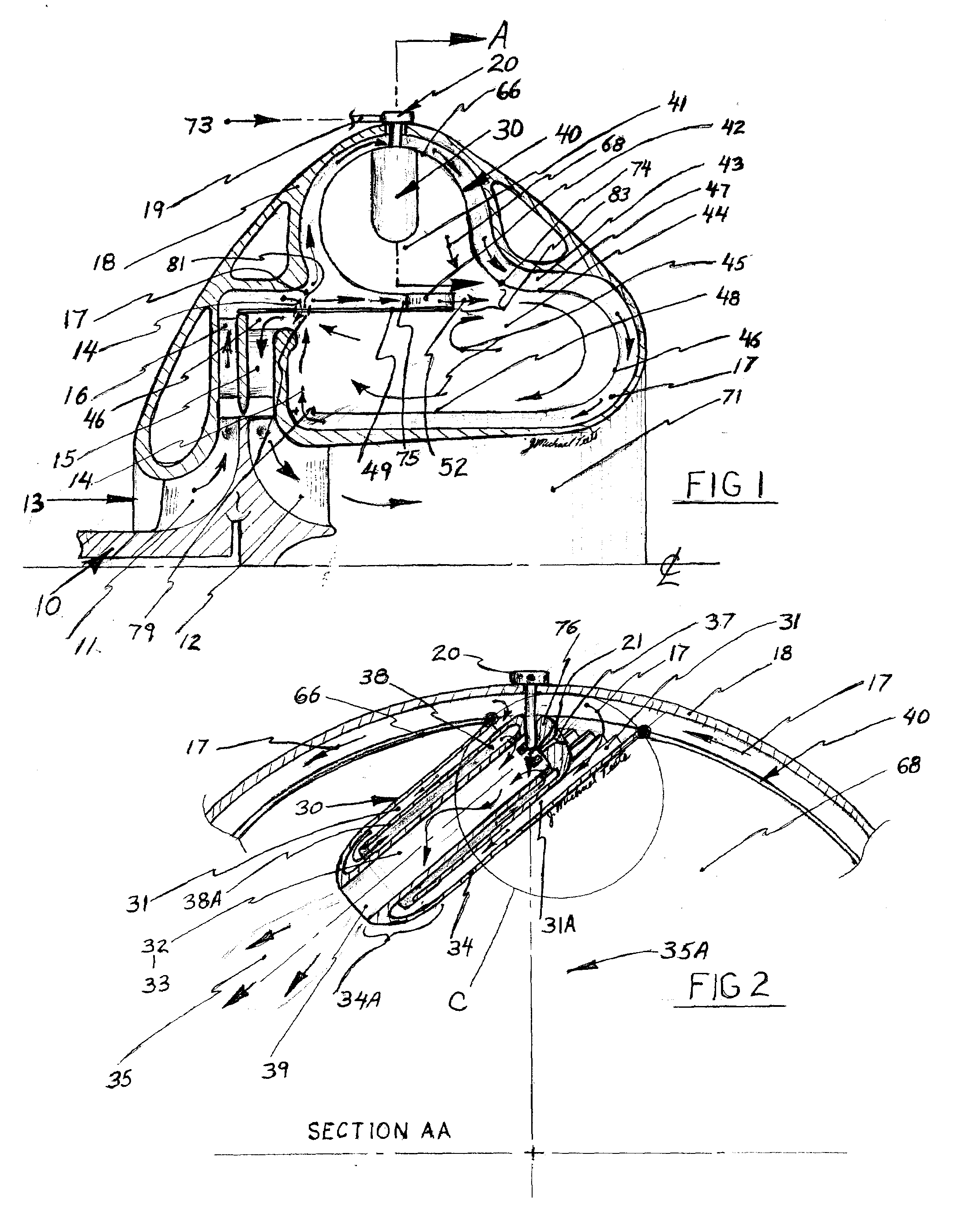
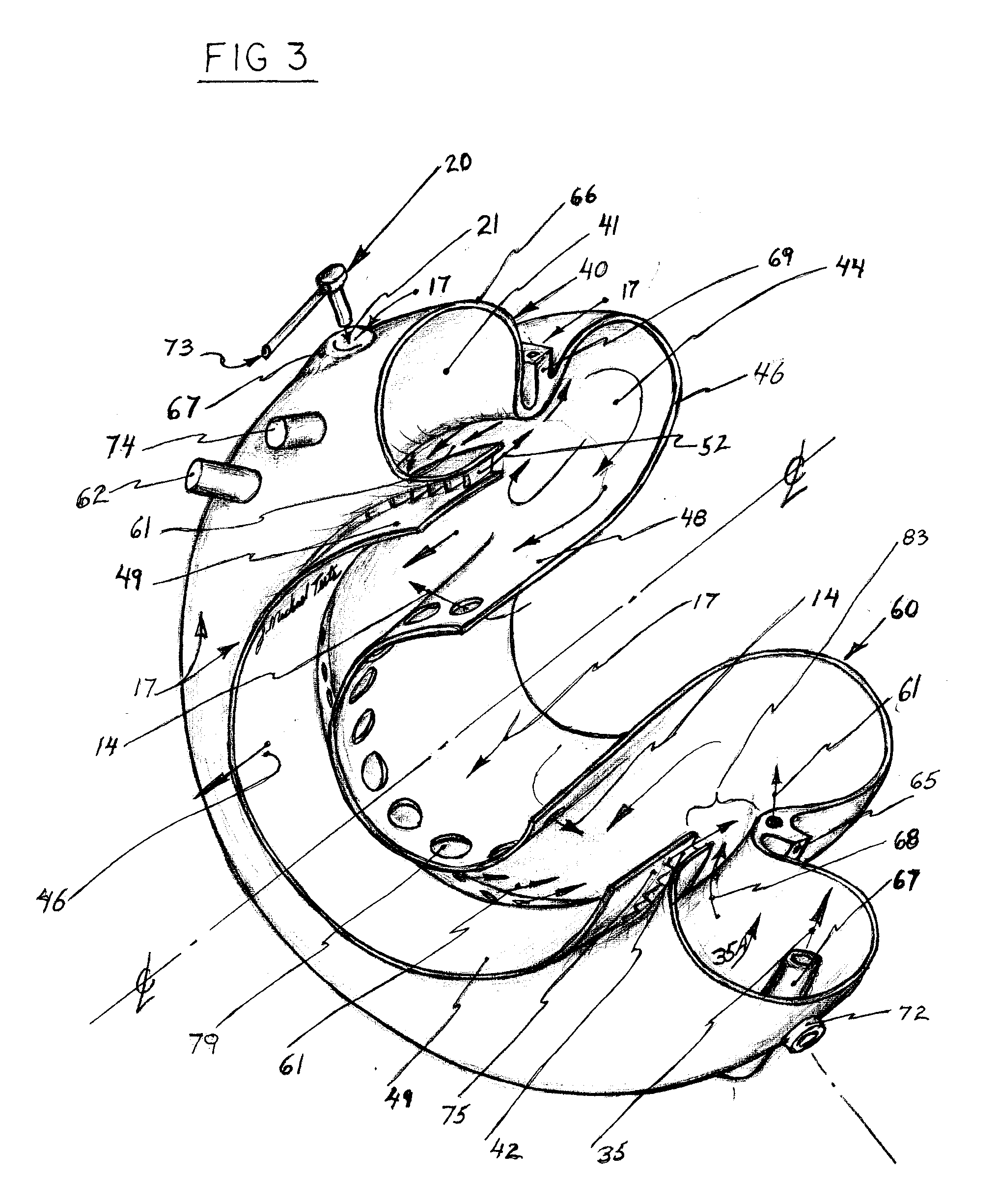
[0029]Turning now descriptively to the drawings, in which similar reference characters denote similar elements throughout the several views, the attached figures illustrate a radially staged RQL combustor assembly with tangential fuel premix-vaporizer chambers, and comprise of: a primary combustion zone with fuel injection means, tangentially oriented primary fuel / air premix chamber assemblies, a secondary air supply area, a reduced combustor flow area to receive secondary air supply for fuel / air premixing, a secondary combustion zone, a dilution air supply area, a dilution zone.

[0030]This Rich burn-Quick quench-Lean burn (RQL) combustor invention having a toroidal geometry primary combustion zone with tangential premix-vaporizers is generally positioned radially outboard of the secondary combustion zone. The fuel / air premix-vaporizer chamber 30 is a longitudinally elongated tubular form assembly with an outer tube 34 having internal cooling means 31 and a co-axial inboard fluid tur...


PUM


Abstract

A double annular radially staged combustor having an axially reduced common internal flow transitioning area between outboard primary combustion zone and inboard secondary combustion zone. The primary zone geometry is generally a toroidal shell form with a radially inboard wall annular exiting thru flow area into the secondary fuel air premixing section. Fuel and Air premixing chambers are incorporated into the primary combustion zone with vaporization capability for liquid fuels. The secondary zone is of an annular shell form, generally inboard and adjacent to the primary zone, accepts the primary combustion gases and mixes with additional supplied air in a reduced annular flow area and then combusted in the secondary combustion zone. The secondary combustion zone exiting gas, flows into a dilution zone where further air is mixed and with continued flow downstream this heat energy is delivered to the turbine stage of a gas turbine engine.

Description

[0001]This application claims benefit of the provisional application Ser. No. 60 / 816404 filed Jun. 26, 2006.BACKGROUND OF THE INVENTION[0002]1. Field of the Invention[0003]This invention relates generally to RQL combustors and more specifically it relates to a radially staged RQL combustor with tangential fuel premixers as an internal combustion energy means for a gas turbine engine to yield low emissions, good flame stability, uniform flame front, mulifuel use including low BTU gas, and good flame stability at any power setting.[0004]2. Description of Prior Art[0005]It can be appreciated that RQL combustors have been in use for years. Typically, low emissions combustors used in gas turbine engines for Dry Low Emissions (DLE) and are either Lean Premixed Prevaporized (LPP) type or Rich burn-Quick quench-Lean burn (RQL) type using liquid or gaseous fuels; the combustors operate with a continuous flame and incorporate fuel nozzle assemblies to accept and premix amounts of regulated de...

Claims


Application Information

Patent Timeline
IPC IPC(8): F23R3/32
CPCF23C2900/06041F23D14/66F23R3/52F23R3/32F23R3/36F23R3/286Y02E20/34
Inventor TEETS, JOSEPH MICHAEL
Owner TEETS JOSEPH MICHAEL MR
Why Eureka
Try Eureka