Tool with an Oscillating Head

a tool and oscillating head technology, applied in the direction of motor/generator/converter stopper, mechanical vibration separation, magnetic body, etc., can solve problems such as homogeneous electric field

Active Publication Date: 2008-02-21
SAUER GMBH
View PDF20 Cites 30 Cited by
  • Summary
  • Abstract
  • Description
  • Claims
  • Application Information

AI Technical Summary

Benefits of technology

[0011] Advantageously, the oscillating motor cooperates with the exciter coil in a touch less fashion. The advantage resulting therefrom is the particularly low-wear operation and the lack of susceptibility, for example to leaking coolant.
[0017] The first and second coils should be positioned over top of each other and surround the tool holder in a circular fashion. This embodiment also allows a touch less excitement of the oscillating motor.
[0019] In all embodiments it is advantageous to embody the tool holder with a coolant channel extending in the axial direction. This embodiment allows not only to cool the tool head but also the oscillating motor.

Problems solved by technology

This results in a particularly homogenous electric field with a constant, evenly intense oscillation of the oscillating motor.

Method used


Image

  • Tool with an Oscillating Head
  • Tool with an Oscillating Head
  • Tool with an Oscillating Head

Examples


first embodiment

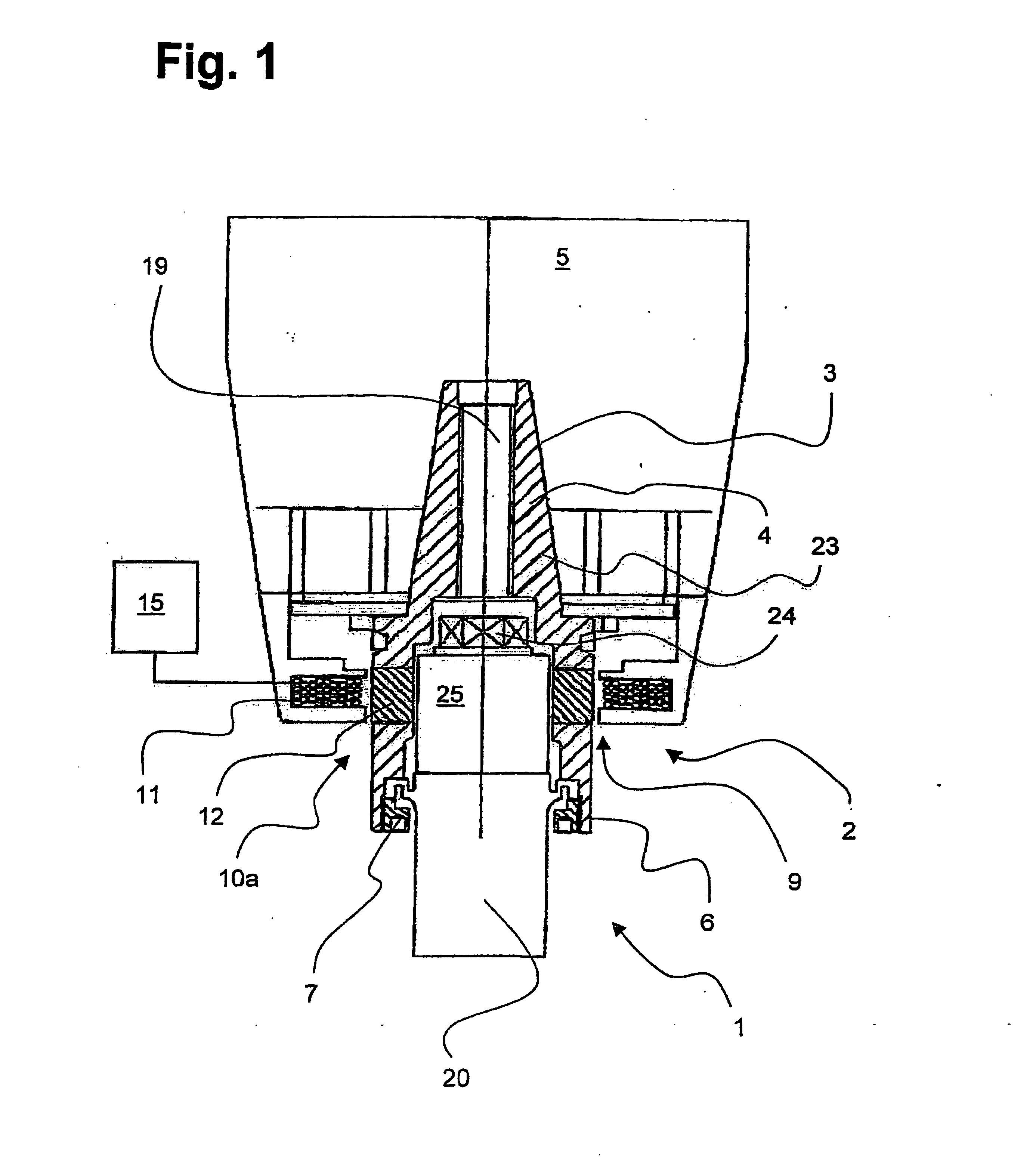
[0025]FIG. 1 shows in a first embodiment a cross-section of a tool holder 2, which is inserted with its conical tool holder recess 4, arranged at the upper end 3, into a spindle driver 5 of an automatic tool, embodied in a complementary manner and not shown in detail, secured against rotation.

[0026] The tool holder 2 is designed in two parts and comprises a carrier element 23 and a primary spindle shaft 20, held by a nut 24, and protruding from the carrier element 23. The torque is transferred from the spindle driver 5 to the tool holder recess 4, which is an integral component of the carrier element 23, and therefrom to the primary spindle shaft 20.

[0027] The primary spindle shaft 20 is additionally supported in a tool recess 7 of the carrier element 23, with said support being a labyrinth bearing allowing the oscillation of the primary spindle shaft 20 in the axial direction.

[0028] A ferro-magnetic head 25 is located on the primary spindle shaft 20, surrounded by a cladding tube...

second embodiment

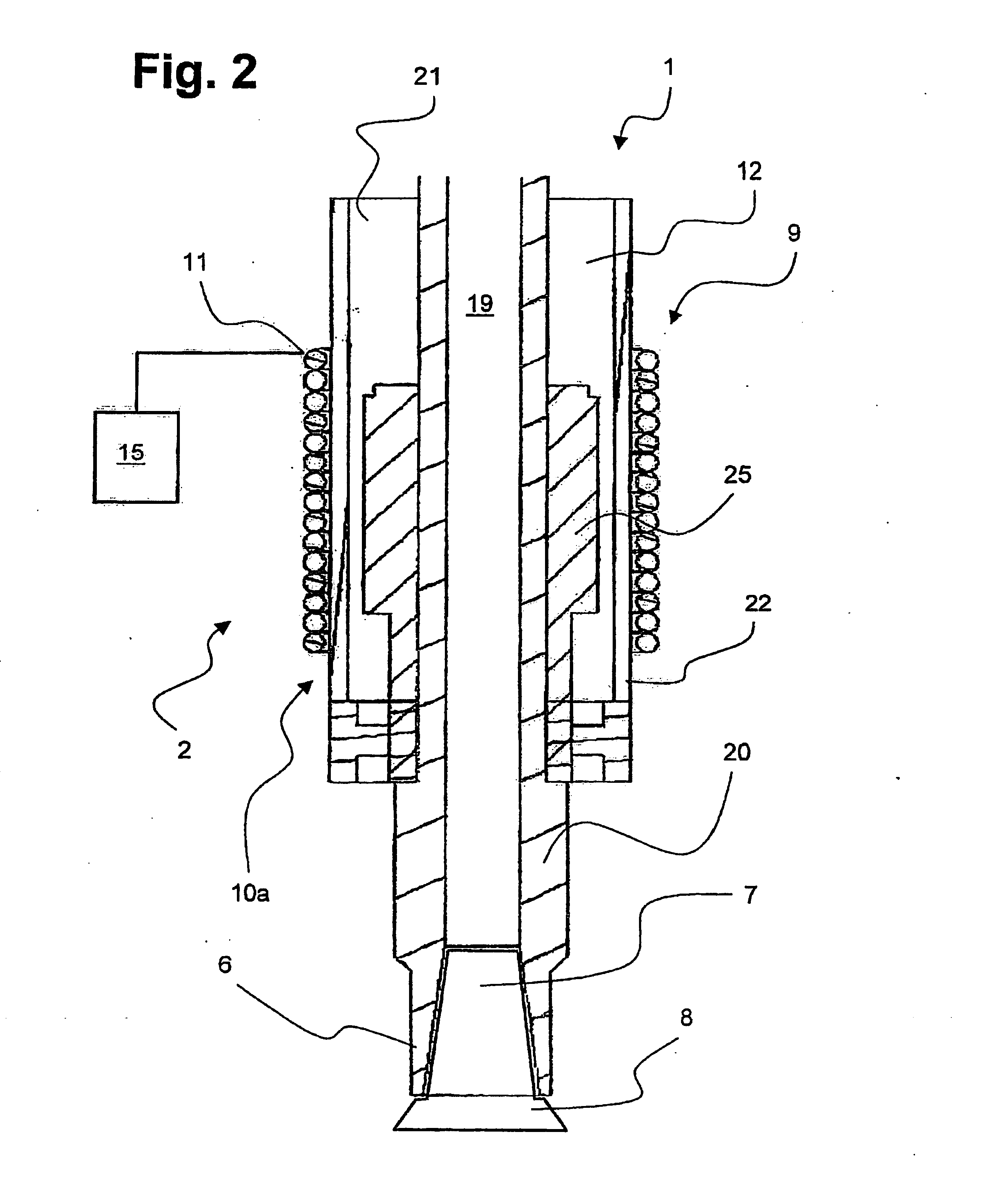
[0031]FIG. 2 shows in a cross-section a tool 1 according to a The tool 1 comprises the tool holder 2, which is provided at its lower end 6 with a conically tapering threaded bore as a tool recess 7. A tool head 8, provided with an also conical thread, is screwed into the tool recess 7.

[0032] The tool holder 2 first comprises a centrally arranged primary spindle shaft 20, extending in a tubular manner from the spindle driver 5, not discernible in FIG. 2, to the tool head 8 mounted at the end. The primary spindle driver 20 transfers the torque of the machine tool to the tool head 8 and furthermore provides for a constant supply of coolant to the tool head 8. For this purpose the primary spindle shaft 20 is embodied in a tubular manner and having a coolant channel 19.

[0033] The ferro-magnetic head 25 is mounted in a torque-proof fashion to the primary spindle shaft 20. Known shaft-hub-connections are used as protection against distortion.

[0034] The ferro-magnetic head 25 is a compon...


PUM

PropertyMeasurementUnit
oscillating frequencyaaaaaaaaaa
non-magneticaaaaaaaaaa
distanceaaaaaaaaaa

Abstract

The invention relates to a tool (1) comprising a tool holder (2), which has on a first end (3) a tool holder recess (4) that is adapted to the contours of a rotating spindle driver (5) and a tool recess (7) on a second end that lies opposite the first end (6). The tool holder also comprises a tool head (8) that can be inserted into the tool recess (7). For the optimal machining of a workpiece, attempts were previously made to provide an oscillating unit in the spindle of the machine, to initiate oscillations in the tool head. The disadvantage of said known constructions is that all available tools have to be synchronized with the oscillation unit. The invention overcomes said disadvantage by equipping the tool holder (2) with an oscillating motor (9).

Description

BACKGROUND OF THE INVENTION [0001] 1. Field of the Invention [0002] The invention relates to a tool with a tool holder and a tool head that can be inserted into the tool holder, with the tool holder at a first end being provided with a tool holder recess for adapting to a rotary spindle driver, and at a second end, opposite the first one, with a tool recess. [0003] 2. Description of Related Art [0004] Commonly machine tools are provided with a rotary spindle, which have a spindle driver at their end, into which, according to the work piece to be processed and the predetermined form, different tools can be inserted, in particular cutting heads. [0005] For an optimum processing of a work piece, in the past some attempts have been undertaken to arrange an oscillating unit at the spindle in the machine, in order to oscillate the tool head. The disadvantage of these known constructions lies in the necessity to adjust all tools available to the oscillating unit. This procedure is very exp...

Claims


Application Information

Patent Timeline
Patent Type & Authority Applications(United States)
IPC IPC(8): B06B1/04B06B1/06B23B31/02B23B37/00
CPCB23B31/02B23B2270/38B23B2260/108B23B37/00
Inventor SAUER, HERMANN
Owner SAUER GMBH
Why Eureka
Try Eureka