Beam director and control system for a high energy laser within a conformal window

a conformal window and beam director technology, applied in the field of optics, can solve the problems of reducing durability and/or increasing manufacturing costs, affecting the performance of conventional adaptive optics systems using deformable mirrors, and delicate optical devices in the path of high-power beams

Active Publication Date: 2008-02-21
RAYTHEON CO
View PDF18 Cites 55 Cited by
  • Summary
  • Abstract
  • Description
  • Claims
  • Application Information

AI Technical Summary

Problems solved by technology

Unfortunately, the use of delicate optical devices in the path of a high-power beam is problematic.
Therefore, coatings may need to be applied at lower than optimal temperature using more complex coating processes, thereby reducing durability and / or increasing manufacturing cost.
In addition, conventional adaptive optics systems using deformable mirrors are limited in performance.
There is also a limitation with respect to the number actuators that can be used.
The stroke of the conventional deformable mirror is limited.
Further, a conventional continuous face sheet deformable mirror cannot correct for a pathology in the spatial phase pattern, such as a branch point or an abrupt phase discontinuity.
However, this scheme is practical only with a coherently combined array of single-mode fiber amplifiers, as each fiber channel is correctable in piston only, not high order.
Also, this scheme is not applicable to multi-mode laser media such as large core fiber amplifiers or bulk media lasers as contemplated for weapon class HEL devices and may not be scaleable to high power levels due to random, high frequency phase noise caused by pump-induced temperature fluctuations within the fibers.
This approach, however, places the LCLV in the high power beam path and is therefore limited by the damage susceptibility of the liquid crystal material.
Unfortunately, as is known in the art, in airborne applications, flat windows are problematic with respect to aerodynamic and optical design and operational considerations.
That is, flat windows tend to be more fragile, impose considerable operational constraints on the system and are not conducive to high performance aerodynamic operation.
However, conformal windows add large-stroke, low-order phase distortions due to lensing as well as chromatic aberration effects resulting from index dispersion, and these must be compensated by the beam control system in order to generate high HEL beam intensity on target.

Method used


Image

  • Beam director and control system for a high energy laser within a conformal window
  • Beam director and control system for a high energy laser within a conformal window
  • Beam director and control system for a high energy laser within a conformal window

Examples


Embodiment Construction

[0023]Illustrative embodiments and exemplary applications will now be described with reference to the accompanying drawings to disclose the advantageous teachings of the present invention.

[0024]While the present invention is described herein with reference to illustrative embodiments for particular applications, it should be understood that the invention is not limited thereto. Those having ordinary skill in the art and access to the teachings provided herein will recognize additional modifications, applications, and embodiments within the scope thereof and additional fields in which the present invention would be of significant utility.

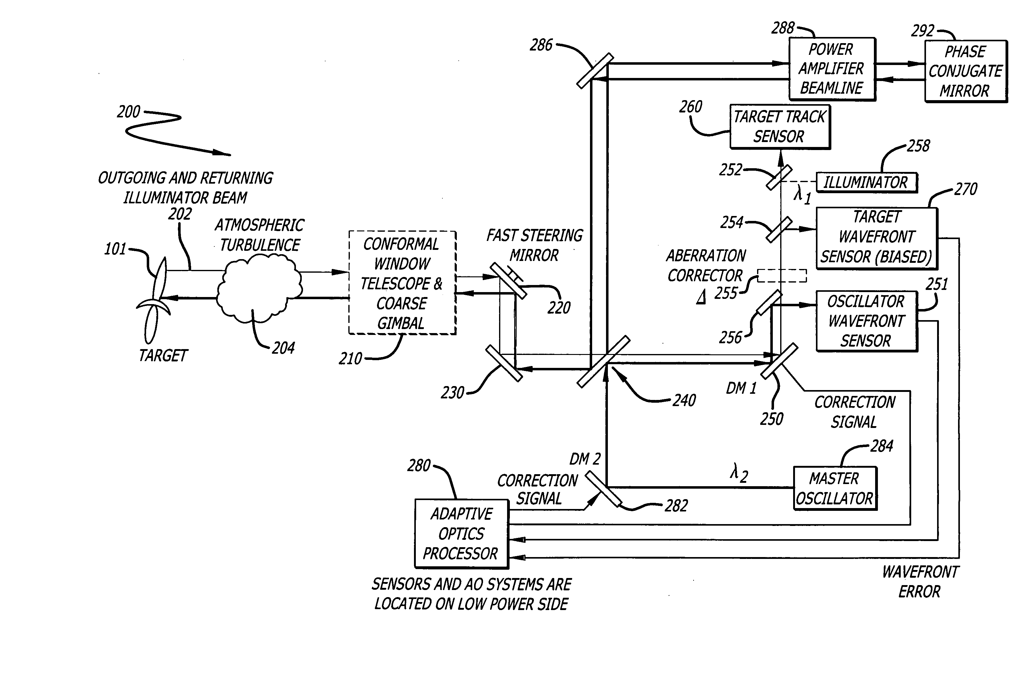
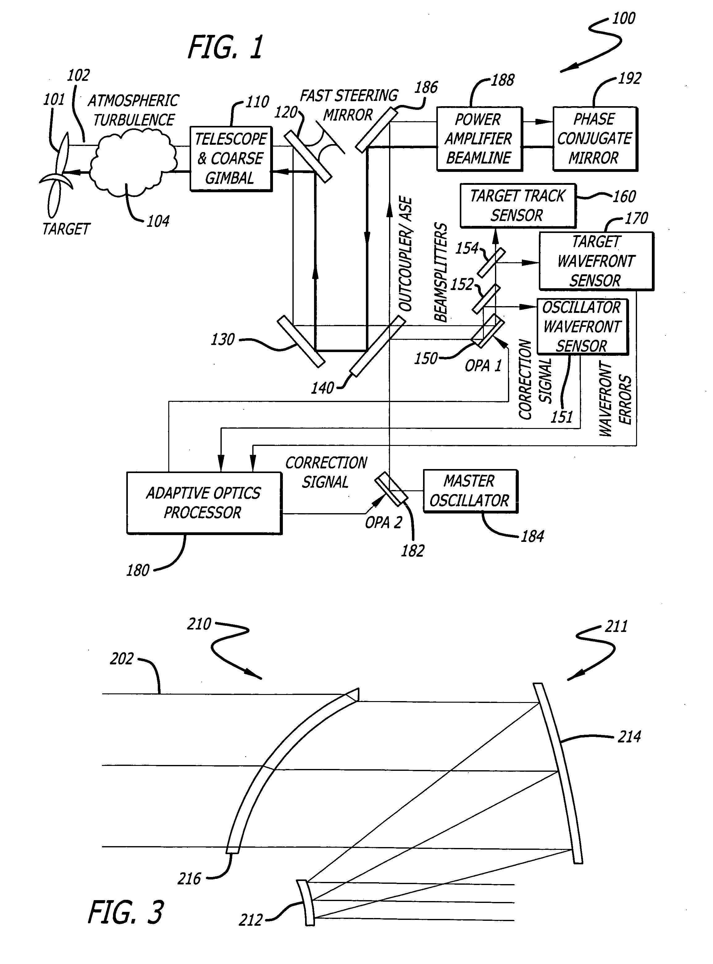
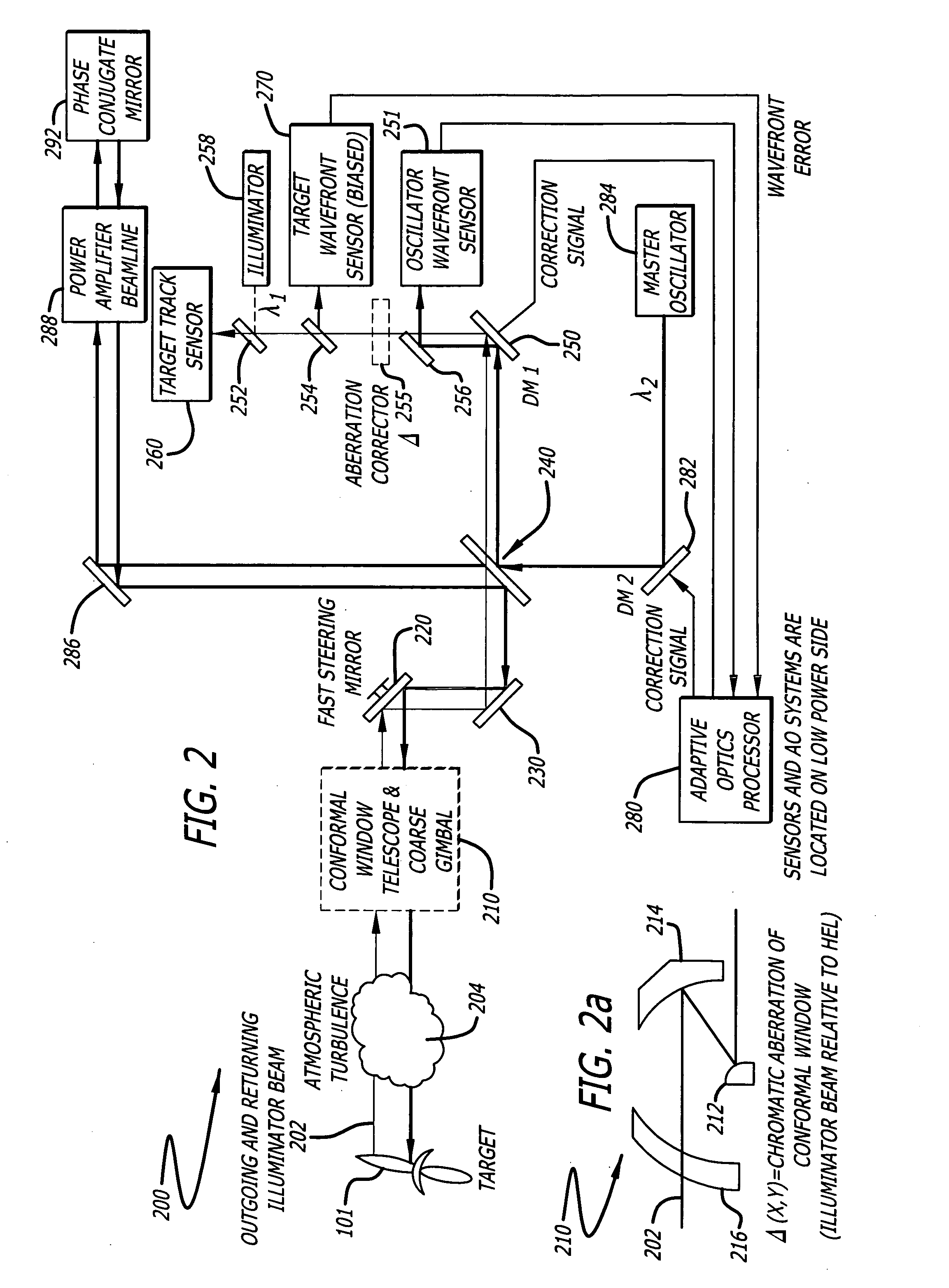
[0025]FIG. 1 is a block diagram of a high-energy, laser beam control system architecture in accordance with the teachings of U.S. Pat. No. 6,809,307, the teachings of which are incorporated by reference herein. The heart of this system is the use of deformable optical elements, liquid crystal optical phased arrays or spatial light modulators in the l...


PUM


Abstract

A beam control system and method. The system includes an illuminator for providing a first beam of electromagnetic energy at a first wavelength; a source for providing a second beam of electromagnetic energy at a second wavelength; and an arrangement for compensating wavefront errors in the second beam using a bias representative of a comparison between the first wavelength and the second wavelength. In the illustrative embodiment, the arrangement includes a processor which corrects wavefront errors using a bias representative of a difference between said first wavelength and said second wavelength. In the disclosed application, a target wavefront sensor is included and the laser is a high-energy laser beam. The wavefront errors include a chromatic aberration and the errors are compensated using a deformable mirror and a correction algorithm executed by an adaptive optics processor. In one alternative embodiment, the errors are compensated using an optical aberration corrector. The aberration corrector may be a holographic optical element or other suitable device. In another alternative embodiment, the errors are corrected with the above embodiment in combination with the use of “woofer” and “tweeter” correcting elements with the woofer being a long stroke low frequency element and the tweeter being a short stroke high frequency element.

Description

BACKGROUND OF THE INVENTION[0001]1. Field of the Invention[0002]The present invention relates to optics. More specifically, the present invention relates to systems and methods for directing and correcting high-power beams of electromagnetic energy.[0003]2. Description of the Related Art[0004]Directed energy weapons and specifically high-energy laser (HEL) weapons are being considered for a plethora of military applications with respect to a variety of platforms, e.g., spaceborne, airborne and land based systems to name a few. These weapons generally involve the use of the laser or other source of a high-power beam to track and destroy a target. To achieve mission objectives, directed energy weapons must be accurately steered and optimally focused. Steering involves line-of-sight control while focusing, which with respect to HEL weapons, necessitates wavefront error correction. Currently, wavefront error correction is typically achieved using adaptive optics. The current state of th...

Claims


Application Information

Patent Timeline
Patent Type & Authority Applications(United States)
IPC IPC(8): G01J1/20
CPCF41H13/005G01S17/66G02B5/32H01S3/005G02B23/06G02B26/06G02B26/0825G02B17/0884
Inventor KING, WILLIAM B.CHEN, CHUNGTE W.BYREN, ROBERT W.MCKEARN, CHAUNCHY F.
Owner RAYTHEON CO
Why Eureka
Try Eureka