

Self tracking ADC for digital power supply control systems
- Summary
- Abstract
- Description
- Claims
- Application Information
AI Technical Summary
Benefits of technology
Problems solved by technology
Method used
Image

Examples
Embodiment Construction
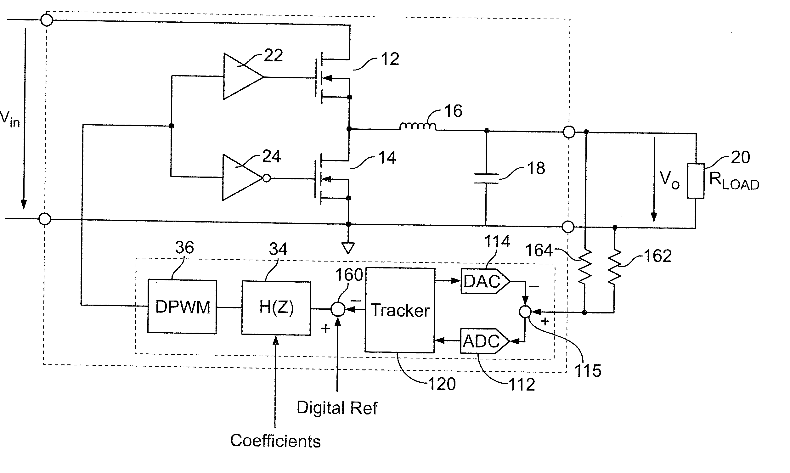
[0027] The present invention provides a method for digitally controlling a switched mode power supply. More specifically, the invention provides an ADC circuit that produces a digital representation of a parameter that needs to be regulated (e.g., the absolute output voltage of a power supply), so that any additional monitoring and supervisory circuits could be implemented as full digital circuits. In the detailed description that follows, like element numerals are used to describe like elements illustrated in one or more figures.
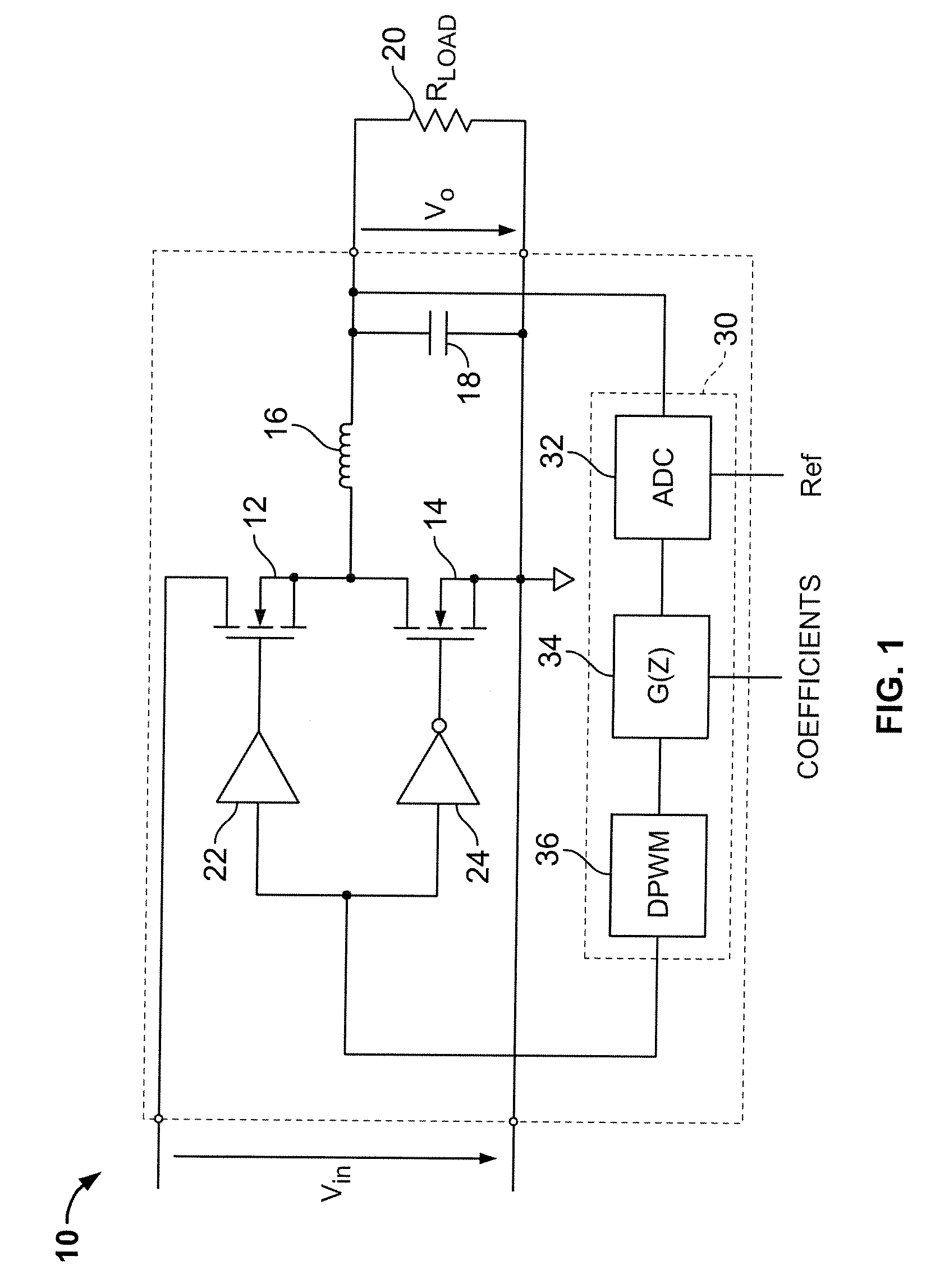
[0028]FIG. 1 depicts an exemplary switched mode power supply 10 having a digital control circuit in accordance with an embodiment of the present invention. The power supply 10 comprises a buck converter topology to convert an input DC voltage Vin to an output DC voltage Vo applied to a resistive load 20 (Rload). The power supply 10 includes a pair of power switches 12, 14 provided by MOSFET devices. The drain terminal of the high side power switch 12 is co...
PUM
 Abstract
Description
Claims
Application Information