Tubular RF cage field confinement cavity

a tube-shaped, cavity-type technology, applied in the direction of accelerators, resonators, electric discharge tubes, etc., can solve the problems of limited access into the cavity, difficult manufacturing of the cavity, and high production cost of the solid cavity design, so as to improve the cooling effect, improve the rf performance, and reduce the spacing

Inactive Publication Date: 2008-02-21
UCHICAGO ARGONNE LLC
View PDF4 Cites 3 Cited by
  • Summary
  • Abstract
  • Description
  • Claims
  • Application Information

AI Technical Summary

Benefits of technology

[0026]In accordance with features of the invention, a cage cavity can be formed by interleaving two or more tube cages to form a cavity. If close spacing between rods is required at the large area of a cavity, the tubes could interfere at the small area of the cavity near the beampipe. To overcome this problem, tube shapes can be formed so that the tubes overlay in the small areas, but the tubes are aligned in the same plane at the large areas. In essence there are two, or more, cages interleaved to form the cavity. Advantages include improved RF performance due to the smaller spacing between tubes, and improved cooling since tube diameters do not have to be made smaller to accommodate closer spacings.

Problems solved by technology

These cavities are difficult to manufacture.
The solid cavity designs can be very expensive to produce due to material costs and fabrication complexity.
The solid cavity design also results in limited access into the cavities for coupling power, diagnostics, damping, and vacuum pumping.
The ports usually degrade the RF performance of a completely solid cavity.
Disadvantages are that the disclosed radio frequency resonant cavity is limited to a simple cylindrical geometry and the use of coolant to allow high power RF operation is not enabled.
In addition, it would be cumbersome to assemble multiple Giordano cells into a multiple cell cavity.
Finally, the Giordano cavity cannot sustain a high quality factor, Q, the ratio of the resonance frequency to the half-power bandwidth.
An accelerating structure is created by removing a rod at the center of the array, thus introducing a defect into the array.
The vacuum pressure in the cavity limited cavity operation.
The slotted cavity was also limited in the amount of RF power that could be introduced to the cavity.

Method used


Image

  • Tubular RF cage field confinement cavity
  • Tubular RF cage field confinement cavity
  • Tubular RF cage field confinement cavity

Examples


Embodiment Construction

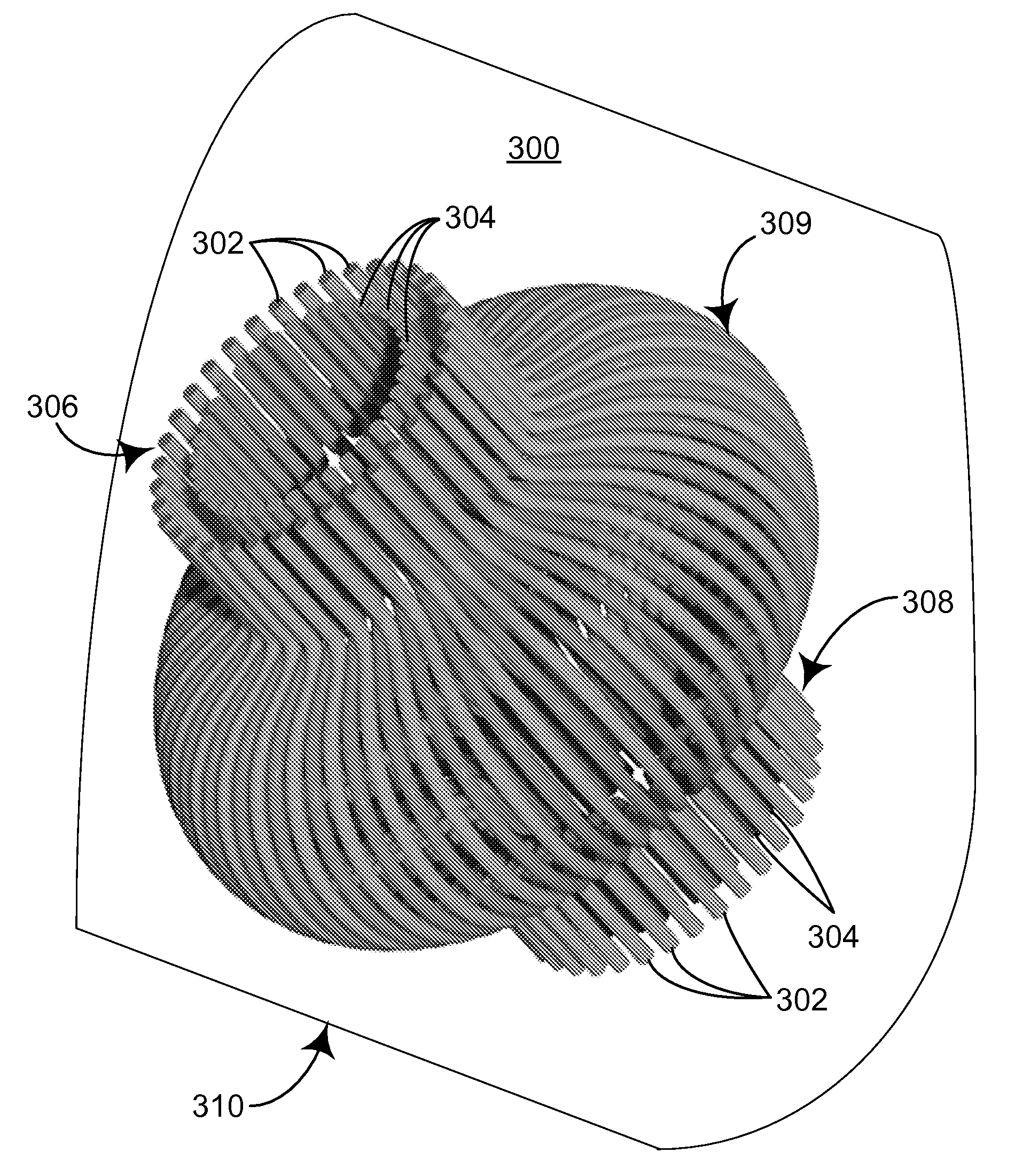
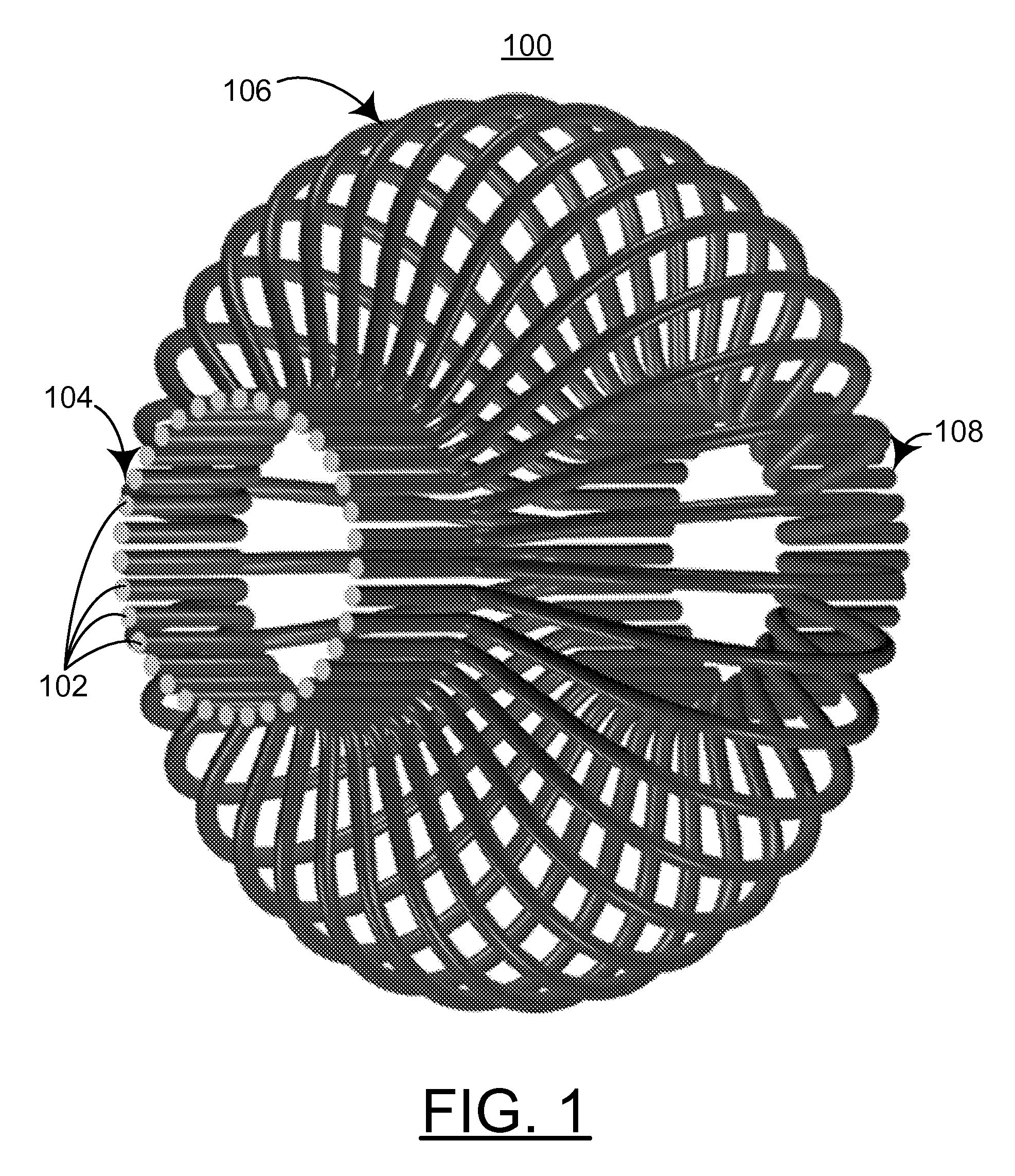
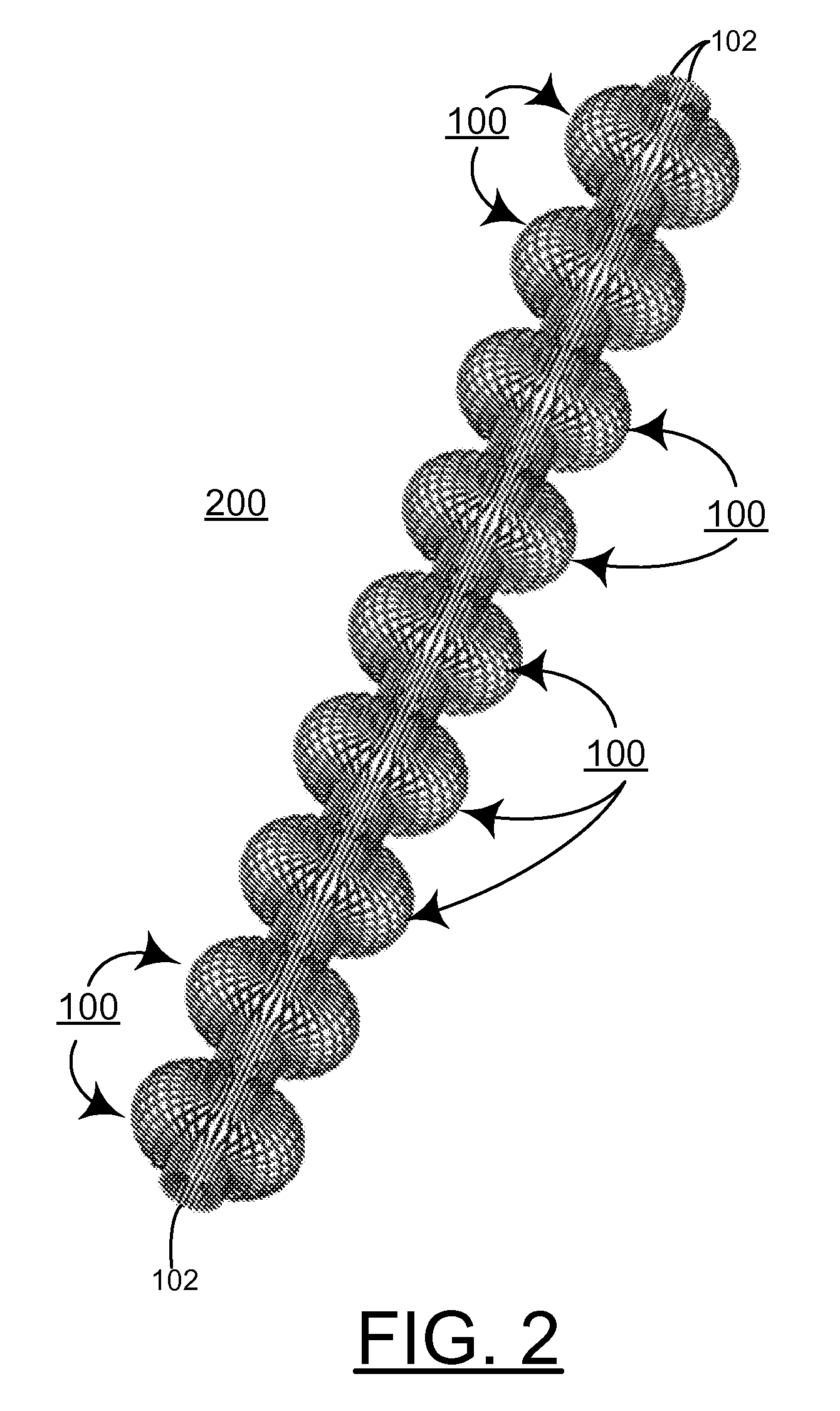
[0033]A particularly important example of an RF cavity is the TESLA cavity that will be used in the proposed International Linear Collider (ILC). The TESLA cavities are solid wall, niobium cavities with a special ellipsoidal shape. The current design for ILC uses a “9-cell” structure that has the best RF performance. There will be 10's of thousands of the cavities installed in the ILC at an estimated cost in the 100's of millions of dollars. Because of this importance, models of cage cavities with the TESLA cavity profile as the volume defined by the cage were made and compared to solid-wall TESLA cavities.

[0034]The physics of a solid wall cavity is that the electromagnetic waves are reflected from the metal wall, i.e. a mirror. It is also known from electromagnetic theory that when a wave, such as a microwave, is incident on a series of equally spaced rods, that waves with frequency below a critical frequency and appropriate polarization (i.e. electric field aligned with the direct...


PUM


Abstract

An RF cavity is provided with a plurality of tubes that are formed into a tubular cage in a predefined shape to define the RF cavity. A selected number of tubes and a selected tube diameter are provided to form a confinement cage for the RF fields within the RF cavity defined by the tubes. The multiple, small metal tubes are selectively bent to form different cavity shapes and sizes as needed to accelerate the particles and function as a confinement cage for the RF fields within the RF cavity defined by the tubes. The cost to fabricate RF cavities using the tubular cage design is significantly lower than the cost of producing a solid cavity using conventional fabrication technology.

Description

[0001]This application claims the benefit of U.S. Provisional Application No. 60 / 818,472, filed on Jul. 3, 2006.CONTRACTUAL ORIGIN OF THE INVENTION[0002]The United States Government has rights in this invention pursuant to Contract No. W-31-109-ENG-38 between the United States Government and The University of Chicago and / or pursuant to Contract No. DE-AC02-06CH11357 between the United States Government and UChicago Argonne, LLC representing Argonne National Laboratory.FIELD OF THE INVENTION[0003]The present invention relates to an improved radio frequency (RF) cavity, and more particularly to an improved design and method of fabrication of an RF cavity.DESCRIPTION OF THE RELATED ART[0004]RF cavities are used to produce very high RF fields to accelerate particles to high energy levels. Present technology confines the fields and encases the ultra-high vacuum environment with a solid metal vessel. With present technology, optimizing the design for RF cavities is a compromise between RF...

Claims


Application Information

Patent Timeline
Patent Type & Authority Applications(United States)
IPC IPC(8): H01P7/06
CPCH01P7/06
Inventor LEWELLEN, JOHN W.NOONAN, JOHNSMITH, TERRY L.WALDSCHMIDT, GEOFF
Owner UCHICAGO ARGONNE LLC
Why Eureka
Try Eureka