Optical scanner and method of controlling optical scanner

a technology of optical scanner and optical scanner, which is applied in the direction of instruments, color television details, printing, etc., can solve the problems of lowering the performance of optical scanner, and achieve the effect of performing stable optical scanning and stable optical scanning

a technology of optical scanner and optical scanner, which is applied in the direction of instruments, color television details, printing, etc., can solve the problems of lowering the performance of optical scanner, and achieve the effect of performing stable optical scanning and stable optical scanning

US20080043295A1Inactive Publication Date: 2008-02-21BROTHER KOGYO KK

Image

  • Optical scanner and method of controlling optical scanner
  • Optical scanner and method of controlling optical scanner
  • Optical scanner and method of controlling optical scanner

Examples


Embodiment Construction

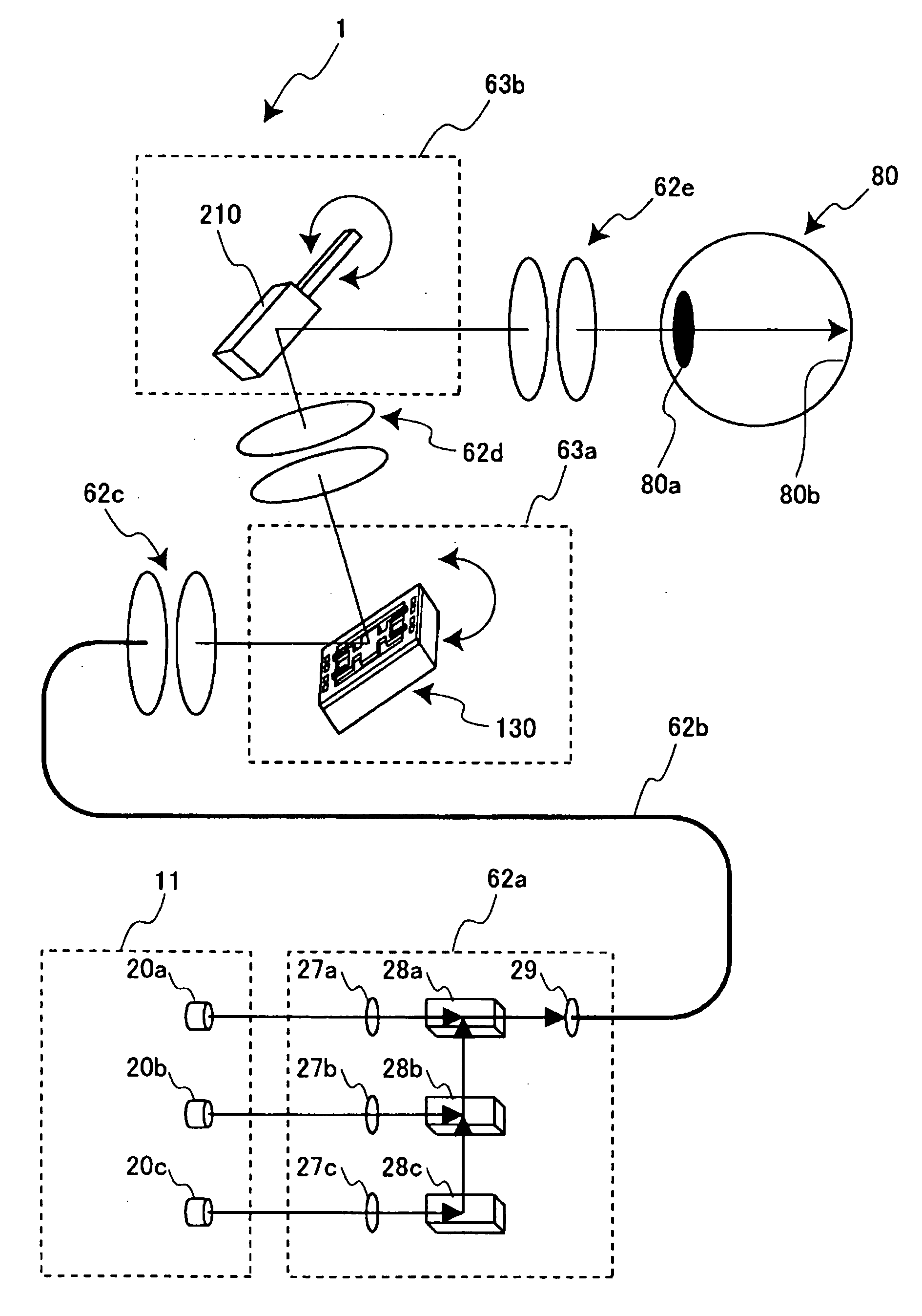
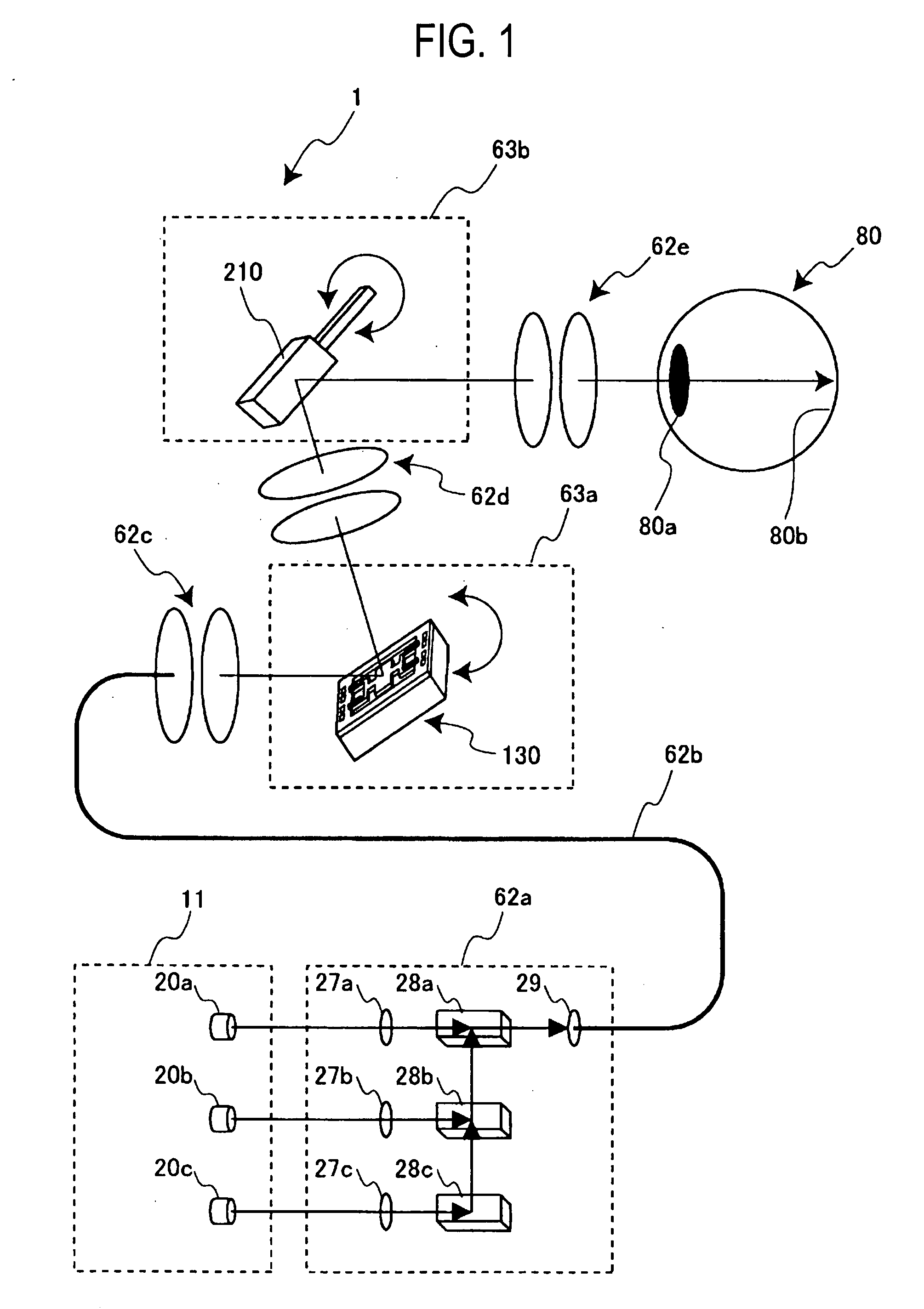
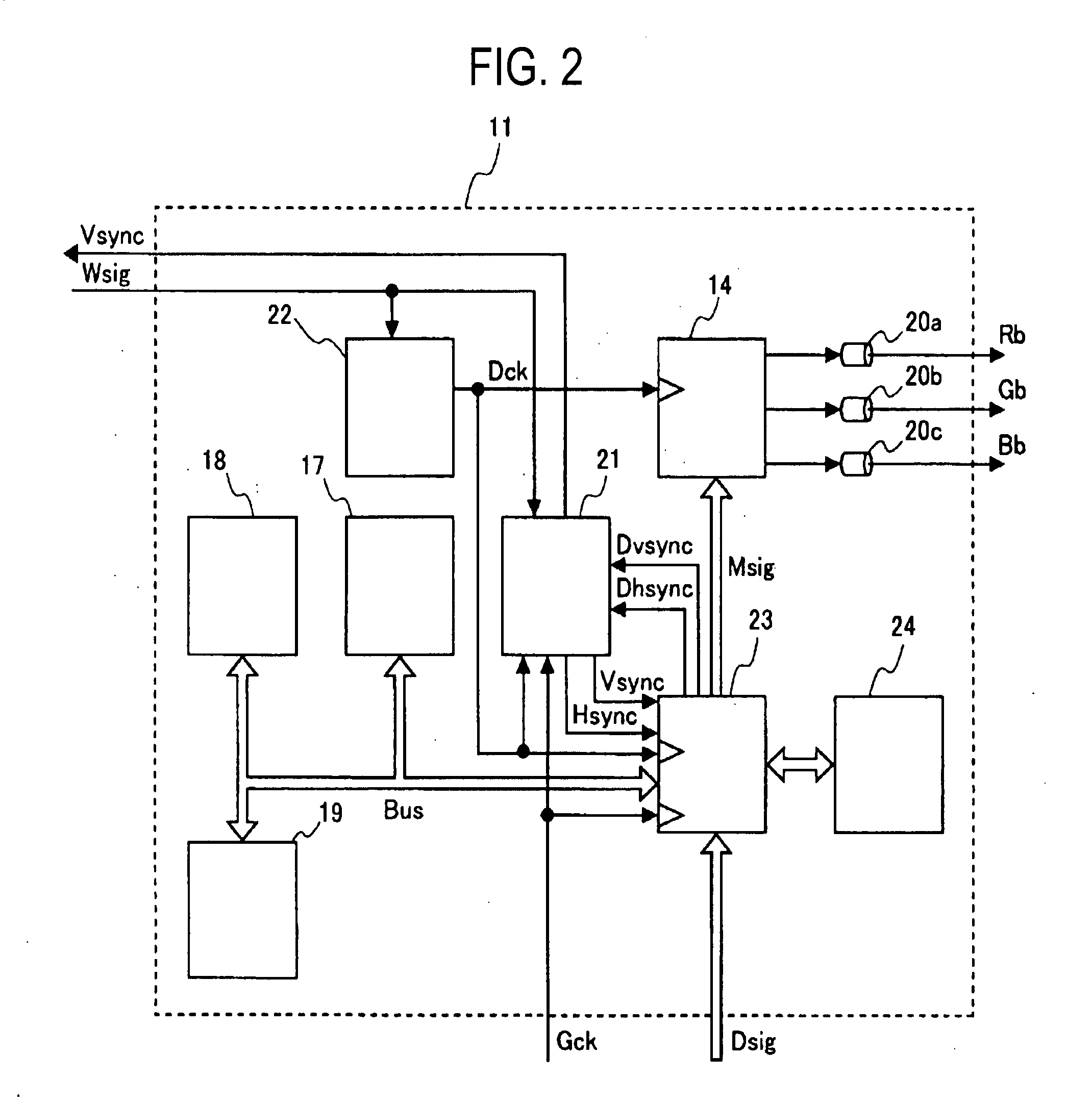
[0035] An optical scanner according to this embodiment which includes a light beam generating part which generates light beams in response to an image signal, an optical path part which guides the light beams to a projection screen, and an optical scanning part which changes the radiation direction of the light beams, wherein the optical scanning part includes an oscillation-type optical scanning mechanism which includes a movable member which resonates at a predetermined resonance frequency for changing the radiation direction of the light beams, a drive signal generator which generates a drive signal for allowing the oscillation-type optical scanning mechanism to resonate at the resonance frequency, and an oscillation signal generator which generates an oscillation signal in response to a change of the radiation direction of the light beams, and the light beam generating part includes a dot clock generator which generates a dot clock which becomes the reference of time-series proc...


PUM


Abstract

An optical scanner has an oscillation-type optical scanning mechanism which includes a movable member which resonates at a predetermined resonance frequency, a drive signal generator which generates a drive signal for allowing the movable member to resonate at the resonance frequency, and an oscillation signal generator which generates an oscillation signal in response to a change of the radiation direction of the light beams. Here, the oscillation signal generator includes a dot clock generator which generates a dot clock which becomes the reference of time-series processing by setting a frequency of the oscillation signal as a reference frequency.

Description

BACKGROUND OF THE INVENTION [0001] The present invention relates to an optical scanner and a method of controlling the optical scanner, and more particularly to an optical scanner which scans light beams by oscillating a movable member at intrinsic resonance frequency thereof and a control method of the optical scanner. [0002] An optical scanner which is represented by a laser beam printer or a projector which projects an image by scanning light beams has been conventionally used in various industrial fields. Such an optical scanner adopts an optical scanning mechanism which changes the direction of light and, recently, as a type of the mechanism, an oscillation-type optical scanning mechanism has been attracting attentions from a viewpoint of miniaturization of the device. [0003] In one conventional example of the oscillation-type optical scanning mechanism, light beams are scanned such that an oscillating body having a reflecting mirror portion is oscillated so as to change the re...

Claims


Application Information

Patent Timeline
21 Feb 2008
Publication
US20080043295A1
IPC
H04N1/04
CPC
A61B3/1225; B41J2/473; H04N9/3129; G02B26/101; G02B26/0858
Inventors
SAKAKIBARA, MASAHIRO