Honeycomb with a fraction of substantially porous cell walls

a honeycomb and cell wall technology, applied in the field of artificial honeycomb structures, can solve the problems of difficulty and expense in manufacture, limited the performance and applicability of honeycomb type structures in a number of ways, and the movement of heat into air is commonly a rate-limiting step, so as to achieve easy and inexpensive, high surface area to volume ratio, and high effective thermal conductivity

Inactive Publication Date: 2008-02-21
STRAUSS BEN
View PDF30 Cites 63 Cited by
  • Summary
  • Abstract
  • Description
  • Claims
  • Application Information

AI Technical Summary

Benefits of technology

[0012] From the foregoing, there is a need for an easy and inexpensive way to manufacture large, structurally stable arrays of thin-walled fins, with the attendant advantages of high surface area to volume ratio together with high

Problems solved by technology

Through the present, honeycomb has been manufactured with either all substantially solid walls or all substantially porous walls, which has limited the performance and applicability of honeycomb type structures in a number of ways.
Because of the low thermal capacity of air, the movement of heat into air is commonly a rate-limiting step.
Metallic foams have been combined with fins into composite heat exchangers to combat this problem, but the multiple components required for such structures may lead to difficulty and expense in manufacture, especially if the alternating components are densely packed in an attempt to optimize the balance of conduction and heat transfer area.
Furthermore, metallic foams themselves may be expensive to manufacture.
However, fin arrays and pin fin arrays typically achieve significantly lower surface area to volume ratios due to their relative simplicity of structure and the relatively thick fins generally required for inexpensive manufacture and structural integrity.
While these devices and materials have been useful in providing a means of controlling the temperature of a given body or fluid, they have been of limited use in providing advantageous and inexpensive combinations of effective thermal conductivity away from a heat source, and overall surface area to volume ratio.
However, as they do not allow significant transverse fluid flow through their cell walls they a

Method used


Image

  • Honeycomb with a fraction of substantially porous cell walls
  • Honeycomb with a fraction of substantially porous cell walls
  • Honeycomb with a fraction of substantially porous cell walls

Examples


Embodiment Construction

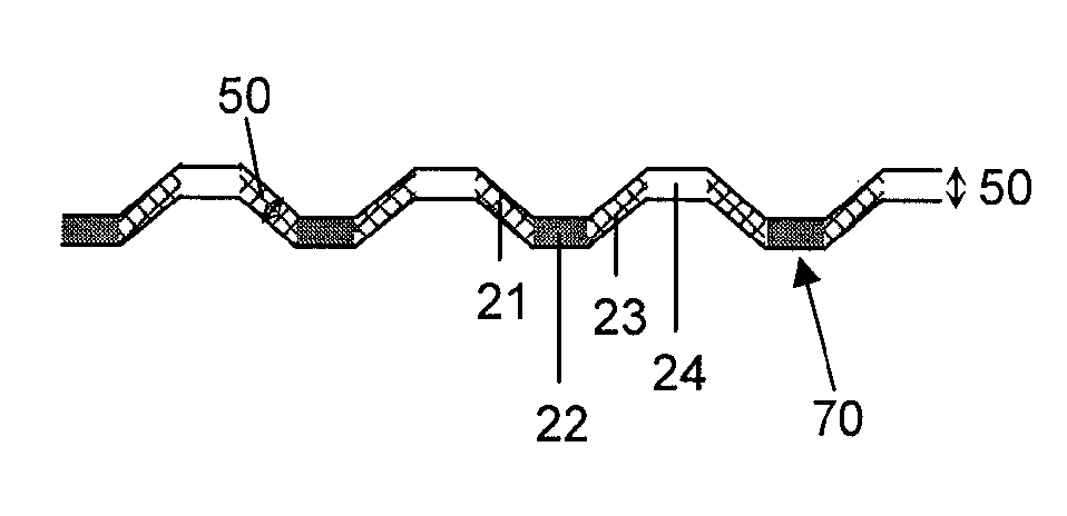
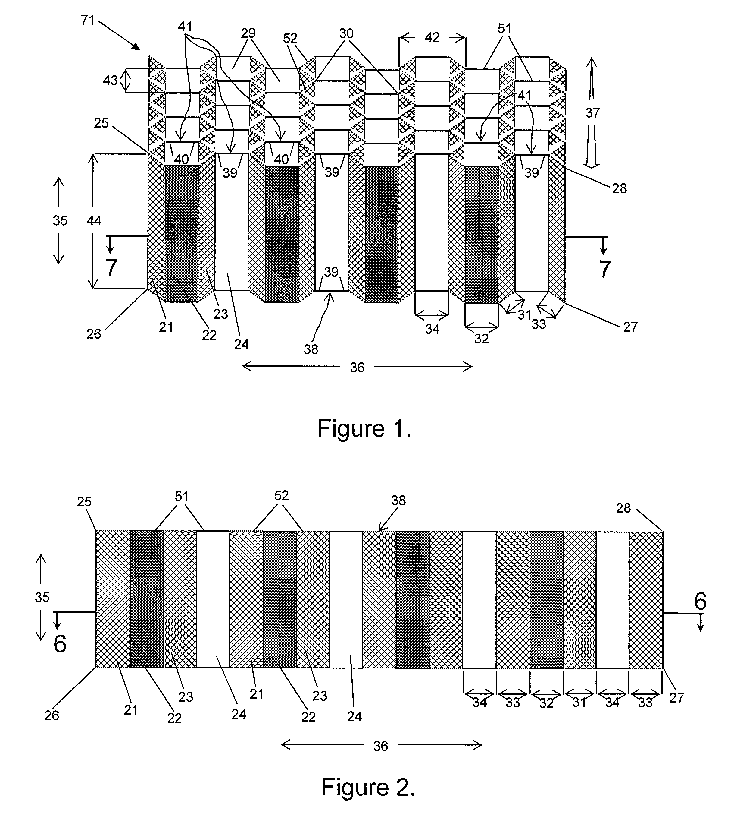
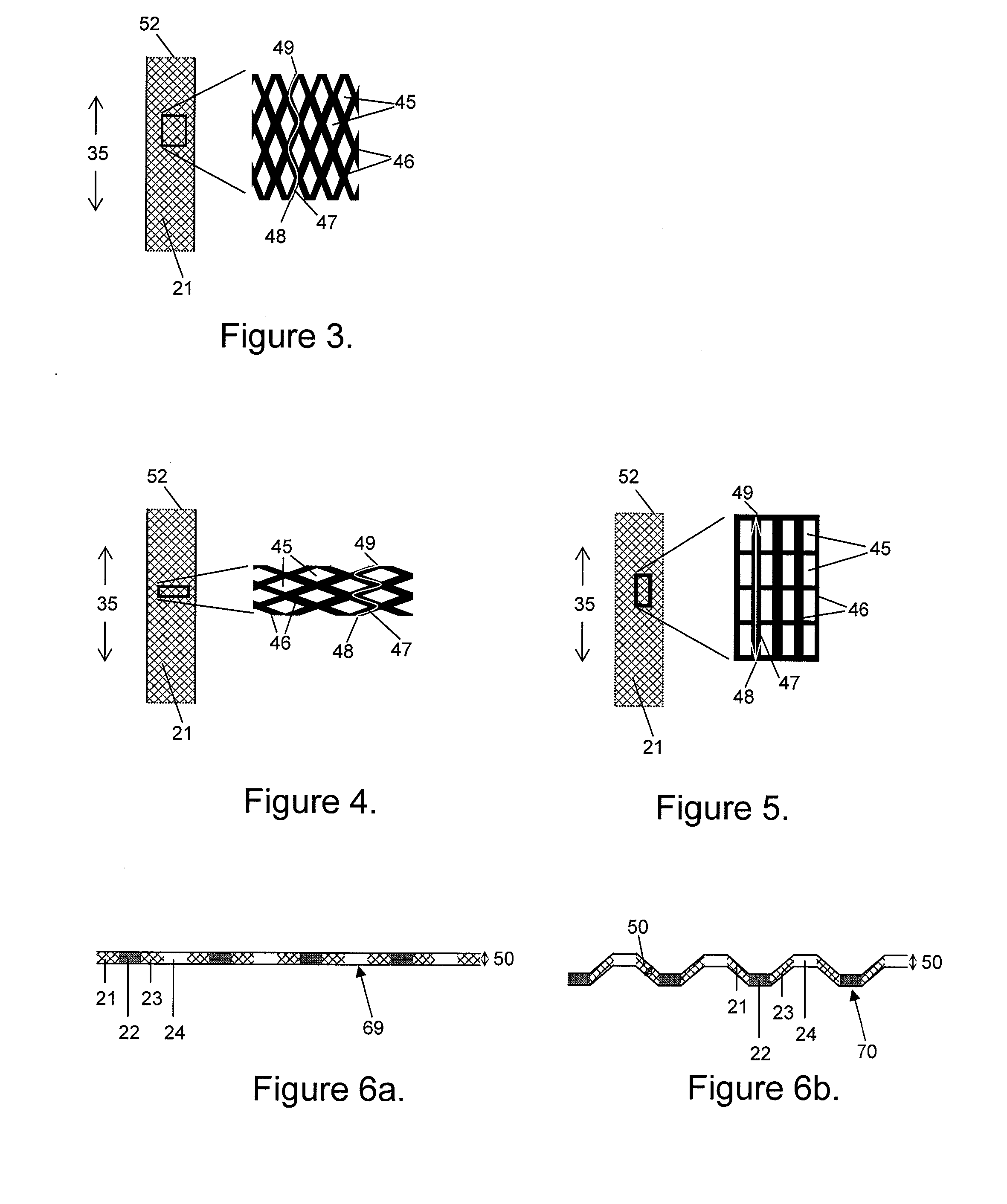
[0078] A honeycomb structure of this invention can include at least two contiguous hollow cells including a plurality of enclosing walls, wherein at least part of at least one of the total number of enclosing walls is substantially porous and at least one is substantially nonporous, and wherein fluid can flow through the at least one porous wall portion. In many embodiments, substantially porous wall portions can comprise entire walls. Solid walls provide advantages that can include, but may be not limited to, strength, impermeability and an effective thermal conductivity equal or near equal to the conductivity of their constituent materials. Porous walls can provide advantages including, but not limited to, permeability to fluid flow, which may include one or more of air flow, water flow, or flow of other gaseous mixtures or liquids, or gases; a high surface area to volume ratio; filtration capability; acoustic dampening capability; relatively light weight per total volume (solid a...


PUM

PropertyMeasurementUnit
Thicknessaaaaaaaaaa
Porosityaaaaaaaaaa
Fractionaaaaaaaaaa

Abstract

An artificial honeycomb structure, and simple constructions therefrom, are provided, wherein at least a portion of at least one of the enclosing honeycomb cell walls is substantially porous, open, or permeable, and wherein at least one of the hollow cells comprises at least one substantially nonporous enclosing wall. The honeycomb and its constructions can be useful in applications that include, but are not limited to, heat exchange and storage, structural support, impact absorption, filtration, acoustic dampening, catalysis, and flow control and distribution.

Description

CROSS-REFERENCE TO RELATED APPLICATIONS [0001] This application claims priority to and the benefit of U.S. provisional patent application Ser. No. 60 / 815,329 filed Jun. 21, 2006, the disclosure of which is being incorporated herein by reference in its entirety.FIELD OF THE INVENTION [0002] The present invention relates generally to the field of artificial honeycomb structures and more particularly to artificial honeycomb structures including both porous and nonporous wall portions. BACKGROUND OF THE INVENTION [0003] Artificial honeycomb structures are used in a wide range of applications, such as for structural support, impact absorption, filtration, acoustic dampening, chemical reaction catalysis, and heat storage and exchange. Through the present, honeycomb has been manufactured with either all substantially solid walls or all substantially porous walls, which has limited the performance and applicability of honeycomb type structures in a number of ways. [0004] One important field...

Claims


Application Information

Patent Timeline
IPC IPC(8): B32B13/12
CPCB22F3/1112B22F3/1115B22F3/1125Y10T428/24083Y10T428/24165Y10T428/24149F28F13/003Y10T428/249953Y10T428/249981Y10T428/249962Y10T428/249988
Inventor STRAUSS, BEN
Owner STRAUSS BEN
Why Eureka
Try Eureka