Discontinuous Transmission Line Structure

a transmission line and discontinuous technology, applied in the direction of waveguide devices, basic electric elements, electrical equipment, etc., can solve the problems of large occupied circuit size, increased wear and tear, and large butler matrix phase array antennas too large for practical use, etc., to suppress high frequency noise signals, compact size, and wide frequency range

Inactive Publication Date: 2008-02-28
WANG CHAO WEI +2
View PDF6 Cites 24 Cited by
  • Summary
  • Abstract
  • Description
  • Claims
  • Application Information

AI Technical Summary

Benefits of technology

[0011]The discontinuous transmission line structures of the present invention are capable of forming transmission lines with a wide v

Problems solved by technology

The implementation of the control circuit for an RFID system operating at 900 MHz has the disadvantage of a large occupied circuit size.
If sizes of the transmissi

Method used


Image

  • Discontinuous Transmission Line Structure
  • Discontinuous Transmission Line Structure
  • Discontinuous Transmission Line Structure

Examples


first embodiment

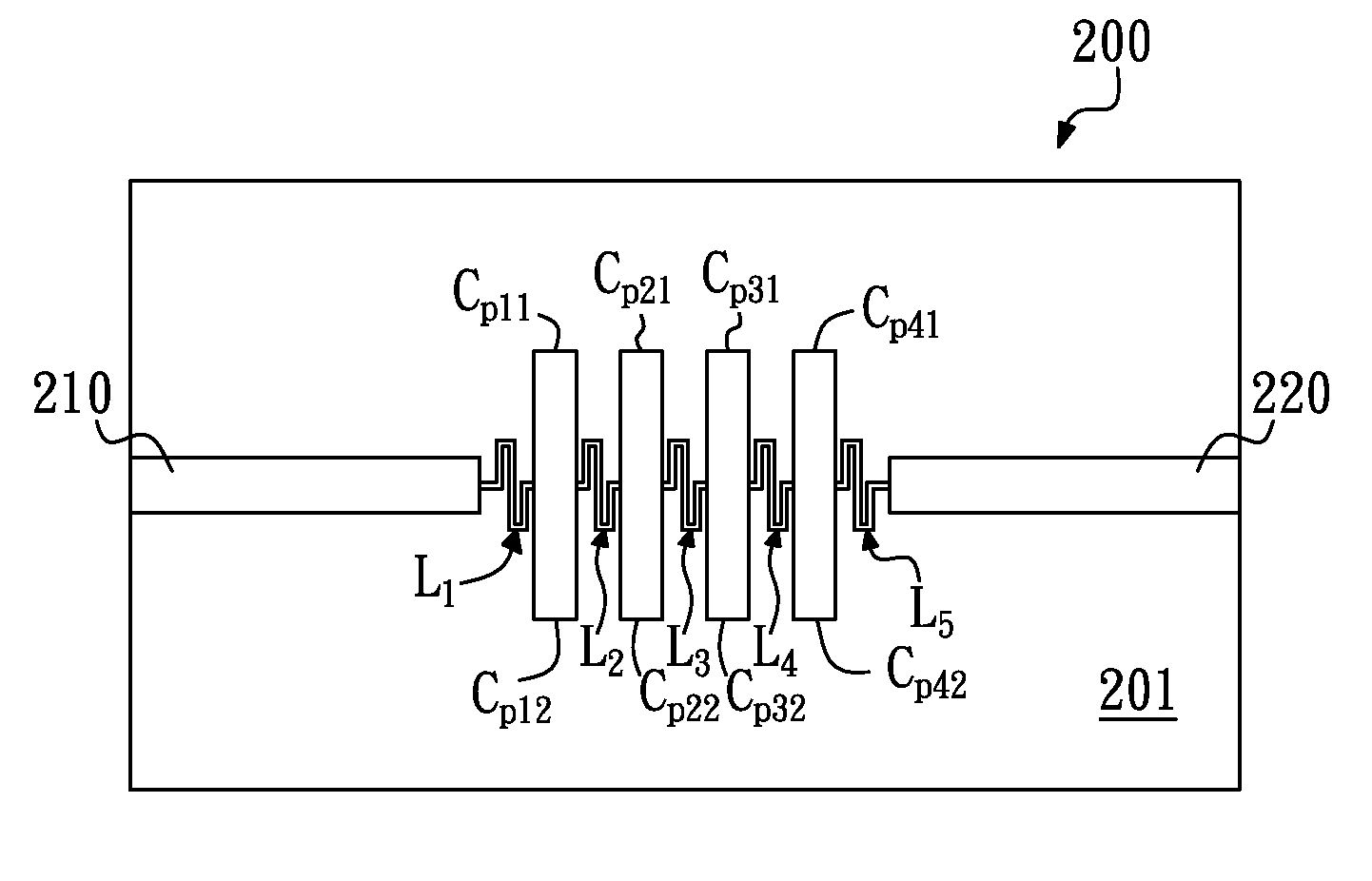
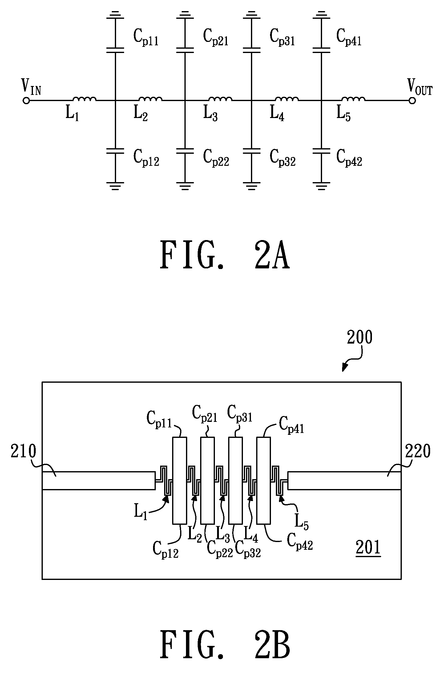
[0024]Referring to FIG. 2A, which shows an equivalent circuit of a discontinuous transmission line structure in accordance with the present invention. The discontinuous transmission line structure includes a capacitor-inductor combination circuit comprising inductors L1, L2, L3, L4, and L5, capacitors Cp11, Cp12, Cp21, Cp22, Cp31, Cp32, Cp41, and Cp42. The inductors L1, L2, L3, L4, and L5 are connected in series between an input VIN and an output VOUT. A pair of the shunted to grounded capacitors Cp11 and Cp12 is connected between the inductors L1, and L2. Similarly, there are also a pair of the shunted to grounded capacitors Cp21 and Cp22 connected between the inductors L2 and L3, a pair of the shunted to grounded capacitors Cp31 and Cp32 connected between the inductors L3 and L4, and a pair of the shunted to grounded capacitors Cp41 and Cp42 connected between the inductors L4 and L5. One end of each of the shunted to grounded capacitors Cp11, Cp12, Cp21, Cp22, Cp31, Cp32, Cp41, an...

second embodiment

[0029]Since the shunted to grounded capacitors Cp11, Cp12, Cp21, Cp22, Cp31, Cp32, Cp41, Cp42 are integrated with the meandered inductors L1, L2, L3, L4, L5 in the manner described above and shown in FIG. 3B, the phase velocity of the second embodiment is reduced and the transmission line circuit can be scaled down.

[0030]Now refer to FIG. 4A, and FIG. 4B. FIG. 4A shows an equivalent circuit of a discontinuous transmission line structure in accordance with a third embodiment of the present invention. FIG. 4B shows a design diagram of the discontinuous transmission line structure 400 of FIG. 4A. The discontinuous transmission line structure shown in FIG. 4A is identical to that shown in FIG. 3A. In contrast with the second embodiment, both ends of two adjacent “I” shaped shunted to grounded capacitors of the third embodiment are interdigital as shown in FIG. 4B. The interdigital shapes, forming the serial capacitors Cg1, Cg2, Cg3, Cg4, Cg5, and Cg6, increases the surface area of the e...


PUM


Abstract

A discontinuous transmission line structure includes an input transmission line, an output transmission line, a plurality of meandered inductors, coupled in series between the input transmission line and the output transmission line, and a plurality of shunted to grounded capacitors, coupled between the meandered inductors. The discontinuous transmission line structure has a high inductance and a high capacitance, and can effectively reduce the size by increasing the transmission line load impedance and capacitance while the characteristic impedance of the transmission line structure remains.

Description

CROSS REFERENCE[0001]The application claims the benefit of provisional application Ser. No. 60 / 830,538, filed Jul. 11, 2006.BACKGROUND[0002]The present invention relates to a transmission line design, and more particularly to a “discontinuous transmission line”, which has elements of high inductance values and elements of high capacitance values.[0003]With the growing popularity of mobile communication systems, beam scanning phase array antenna has become a key element for ensuring accuracy when communicating with users on the move. Similarly, in radio frequency identification (RFID) systems, when goods in storage are being moved around or are placed on a conveyer belt, beam scanning phase array antennas can be implemented to provide better efficiency of RFID readers. Bulter Matrix has an advantage of exactly controlling input signal strength and phase. By integrating Bulter Matrix control circuits to phase array antennas, the phase array antennas have a capability of beam scanning....

Claims


Application Information

Patent Timeline
IPC IPC(8): H01P1/18
CPCH01P1/2039
Inventor WANG, CHAO-WEIMA, TZYH-GHUANGYANG, CHANG-FA
Owner WANG CHAO WEI
Why Eureka
Try Eureka