Wideband Dielectric Resonator Monopole Antenna

a dielectric resonator and antenna technology, applied in the field of antennas, can solve the problems of reducing the operating frequency bandwidth of the antenna, excessive ohmic loss, etc., and achieve the effect of reducing the poor signal reception conditions, easy integration into other planar circuits, and easy manufacturing

Inactive Publication Date: 2008-02-28
NAT TAIWAN UNIV
View PDF2 Cites 27 Cited by
  • Summary
  • Abstract
  • Description
  • Claims
  • Application Information

AI Technical Summary

Benefits of technology

[0006]Another objective of the present invention is to provide a novel antenna, which is a combination of the dielectric resonator and the monopole, with an omnidirectional radiation pattern, for reducing the poor signal reception conditions due to the changes and movements of signal reception location.
[0007]Furthermore, the antenna structure in accordance with the present invention, which mainl

Problems solved by technology

For example, if the wireless LAN 802.11a in the 5.25 GHz frequency band adopts ordinary microstrip antenna, the ohmic loss will be excessive due to high operating frequency.
But increasi

Method used


Image

  • Wideband Dielectric Resonator Monopole Antenna
  • Wideband Dielectric Resonator Monopole Antenna
  • Wideband Dielectric Resonator Monopole Antenna

Examples


Embodiment Construction

[0015]In the following, the present invention will be described in detail with reference to the attached drawings and component numerals, and it can be carried into effect by those skilled in the art after reading it.

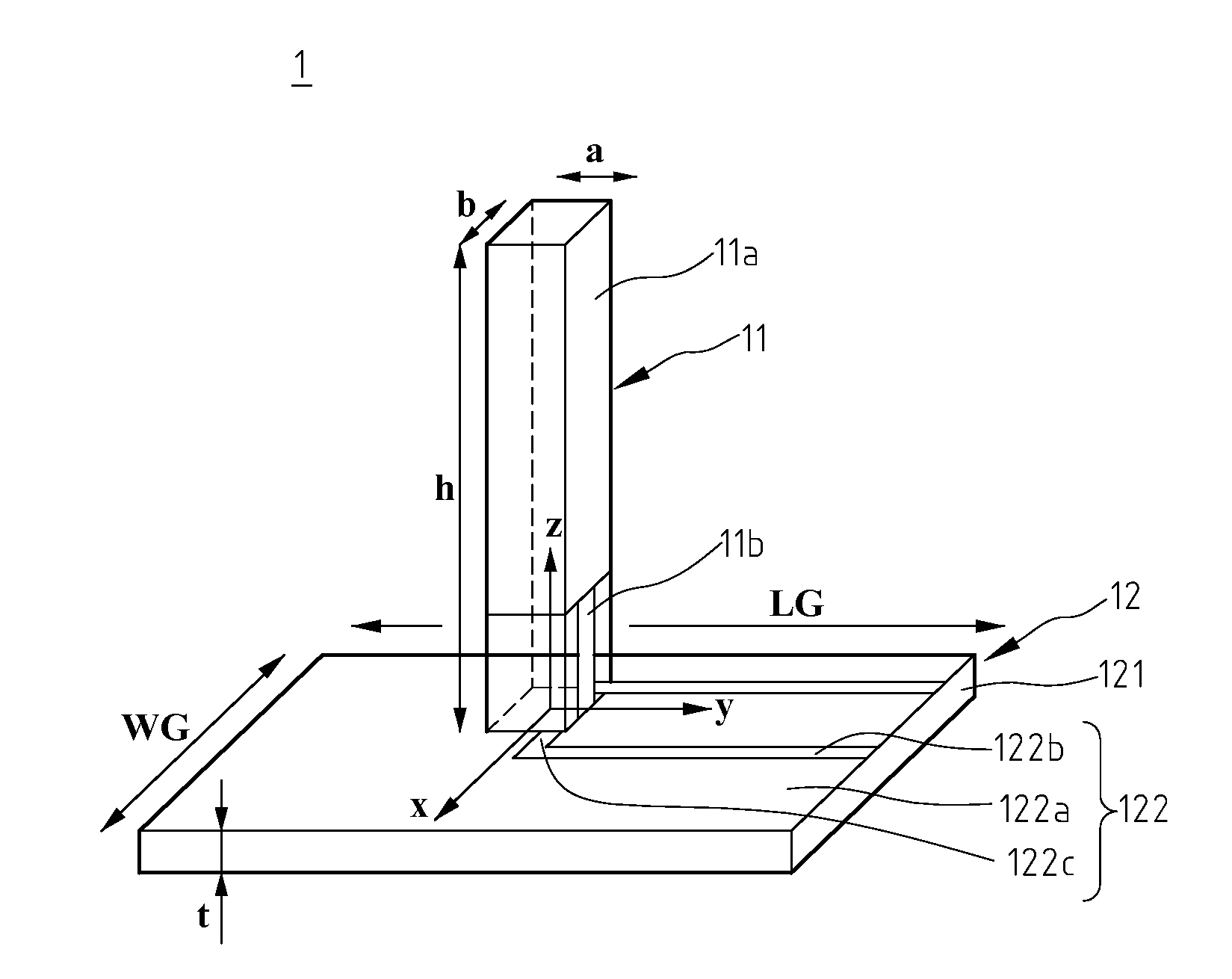
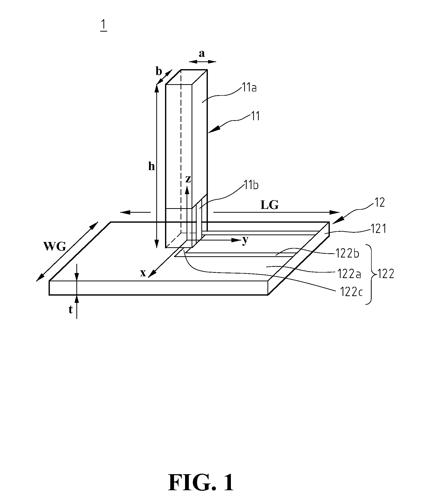
[0016]With reference to FIGS. 1 and 2, an antenna structure 1 in accordance with the present invention is used to receive and transmit signals, which mainly comprises a resonator 11 and a feed-in / feed-out component 12. The resonator 11 can receive electromagnetic signals in the space or transmit electromagnetic signals into the space. The feed-in / feed-out component 12 is used to import or export the signals received or transmitted by the resonator 11.

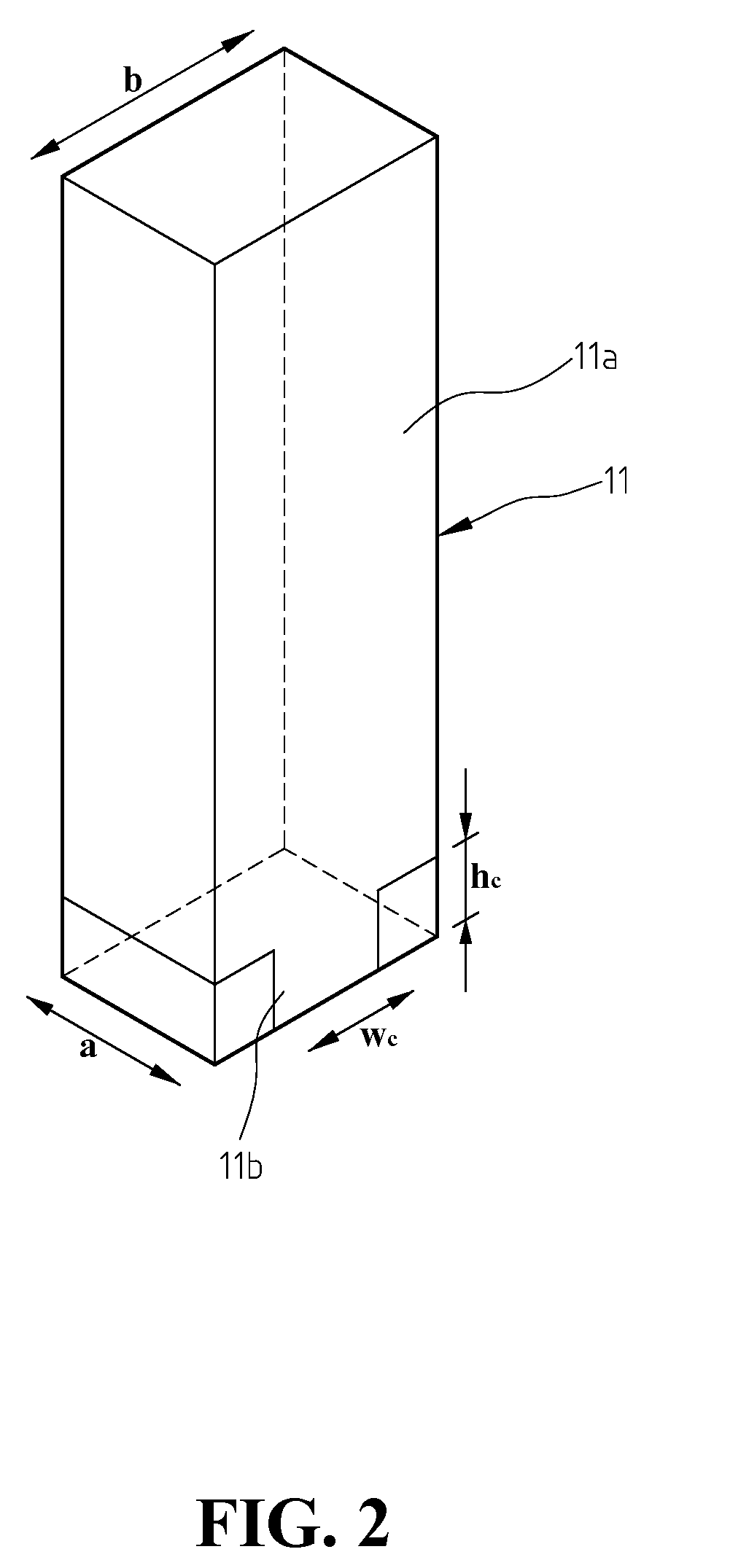
[0017]In the above-mentioned antenna structure in accordance with the present invention, the resonator 11 is a column structure. Part of the exterior surface of the resonator 11 is coated with a metal layer 11a, which is made of conductive material, and a connector 11b is formed at the bottom end of the metal layer 11a, to ...


PUM


Abstract

A wideband dielectric resonator monopole antenna, which includes a dielectric resonator and a monopole antenna, combines two frequency bands having close resonant frequencies to achieve 49% of bandwidth and omnidirectional radiation patterns within the frequency band. It includes a column structure and a substrate, wherein the surface of the column structure is coated with a conductive layer, the column structure is kept upright to the substrate, and the substrate is coated or printed with two slot lines extended inward from an edge of the substrate.

Description

BACKGROUND OF THE INVENTION[0001]1. Field of the Invention[0002]The present invention relates to an antenna combining a dielectric resonator with a monopole.[0003]2. The Prior Arts[0004]With the advancement of wireless communication technology, portable devices have been widely used in various applications, such as industry, science, and medicine, and is also getting more diversified. Their major requirements are portability and low power. Therefore, how to reduce the size and power consumption of the product become important design considerations. For example, if the wireless LAN 802.11a in the 5.25 GHz frequency band adopts ordinary microstrip antenna, the ohmic loss will be excessive due to high operating frequency. Since the dielectric resonator basically has no ohmic loss, it has the advantages of low loss rate, high radiation efficiency and high gain, and is extremely suitable to be operated in high frequency. However, the dielectric constant of the prior dielectric resonators...

Claims


Application Information

Patent Timeline
IPC IPC(8): H01Q1/38
CPCH01Q9/0485H01Q21/28H01Q9/40
Inventor CHANG, TZE-HSUANKIANG, JEAN-FU
Owner NAT TAIWAN UNIV
Why Eureka
Try Eureka