Liquid crystal display device

a display device and liquid crystal technology, applied in the field of liquid crystal display devices, can solve the problems of high power consumption, easy to run down the battery, and difficult to see the image in dark places

Active Publication Date: 2008-02-28
JAPAN DISPLAY WEST
View PDF5 Cites 42 Cited by
  • Summary
  • Abstract
  • Description
  • Claims
  • Application Information

AI Technical Summary

Benefits of technology

[0011]An advantage of some aspects of the present invention is to provide a liquid crystal display device in which the ambient light photosensor is built into the liquid crystal display panel so as not to be affected by external noise and the peripheral circuits.
[0012]Another advantage is to provide a liquid crystal display device in which the ambient light photosensor and the output line leading out from the ambient light photosensor are incorporated in such a manner as not to be affected by external noise and the peripheral circuits.
[0013]Further another advantage is to provide a liquid crystal display device in which the ambient light photosensor and the output line are electrostatically shielded in a simple manner without increasing the fabrication processes for the liquid crystal display panel.

Problems solved by technology

In liquid crystal display panels the liquid crystals are non light-emitting, which means that the images displayed are hard to see in dark places.
Such manipulations are bothersome, and furthermore when it is bright one sometimes ends up turning the backlight on unnecessarily, which wastefully increases the power consumption and, where the display is used in a mobile telephone or similar equipment, could cause the battery to run down quickly.
Since the TFT ambient light photosensor utilizes this leakage current to sense the brightness of the external light, and the leakage current is extremely feeble, the output from the TFT ambient light photosensor is susceptible to the influence of external noise.
Therefore, if the aforesaid ambient light photosensor is built into one of the liquid crystal display panel's substrates, for example into the active matrix substrate (also called the array substrate), then since there are peripheral drive circuits for driving the liquid crystal, as well as external terminals, etc., deployed on the active matrix substrate, high-frequency signals and heat emissions, etc., from such circuits, etc., may affect the sensor.
Consequently these lead lines, particularly the output line, will be susceptible to the influence of external noise.
Moreover, since parasitic capacitance is generated between the output line and the common electrode on the opposed substrate, there is danger that the output line will be affected by the common electrode voltage (below, “VCOM voltage”) that is applied to the common electrode.
This makes the fabrication troublesome and leads to a sharp rise in overall cost.
This means that the transparent electrode acts as an electrostatic shield that renders the ambient light photosensor unlikely to be affected by external noise and the peripheral circuits, and therefore able to sense external light with high sensitivity, so that errors in the control of the illuminating unit will be few.

Method used


Image

  • Liquid crystal display device
  • Liquid crystal display device
  • Liquid crystal display device

Examples


first embodiment

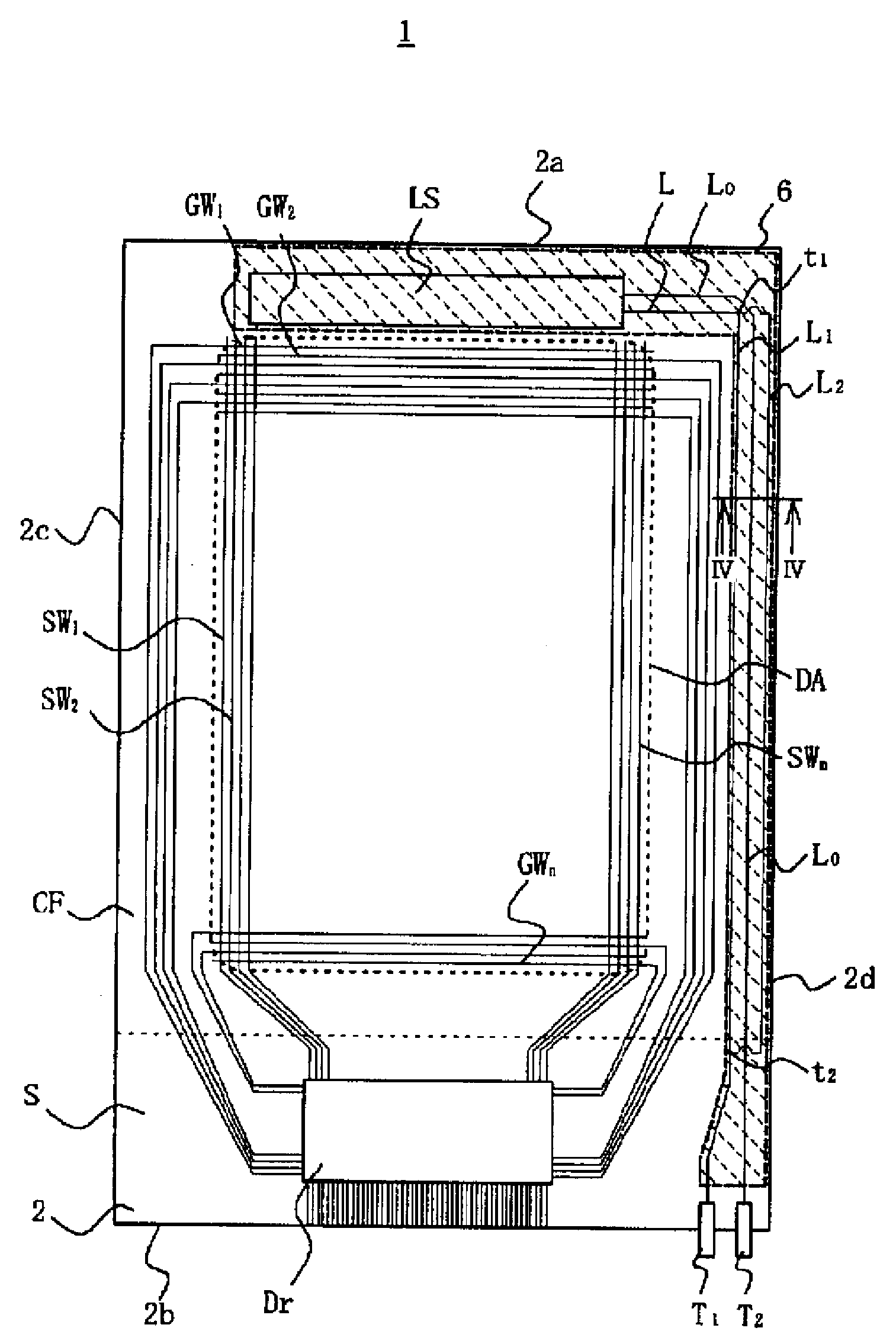
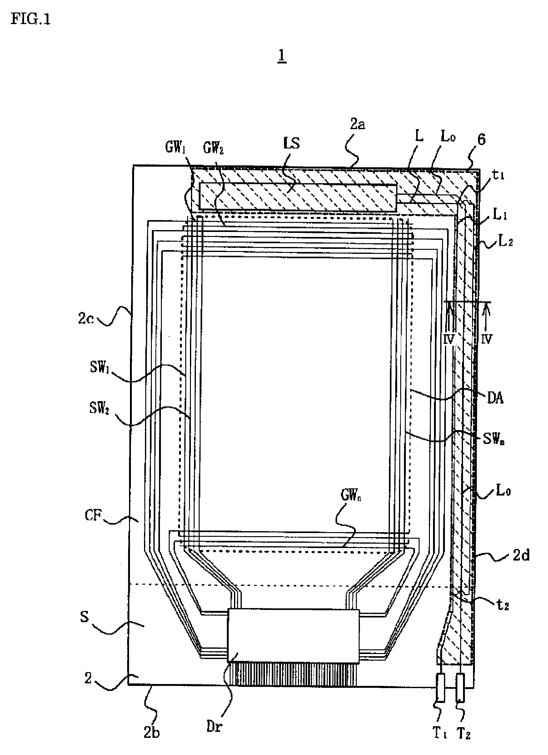
[0061]FIG. 1 is a plan view illustrating schematically the TFT substrate in a liquid crystal display panel of a First Embodiment of the present invention, seen through the color filter substrate.

[0062]As FIG. 1 shows, a liquid crystal display panel 1 has a pair of rectangular substrates, namely an active matrix substrate (below, “TFT substrate”) 2 and a color filter substrate CF, that are constituted of a transparent material such as glass and deployed opposing each other. The TFT substrate 2 is of a larger size than the color filter substrate CF, so that when it is positioned opposing the color filter substrate CF, an overhang portion S of a particular extent is formed. The structure is such that seal material is stuck around the peripheries of the TFT substrate 2 and color filter substrate CF, and liquid crystal and spacers are sealed into the interior space therebetween.

[0063]On the opposed faces of the TFT substrate 2 and color filter substrate CF, there are formed various wirin...

second embodiment

[0085]FIG. 6 is a schematic plan view of the TFT substrate in a Second Embodiment of the invention, seen through a liquid crystal display panel's color filter substrate, and FIG. 7 is a cross-sectional view along line VII-VII in FIG. 6.

[0086]Compared with the liquid crystal display panel 1 of the First Embodiment, a liquid crystal display panel 1A of the Second Embodiment has a similar structure, except that the power line and output line are disposed in a stacked arrangement. Below, accordingly, the structural elements that are in common with the First Embodiment are assigned the same reference numerals as before, and only those elements that differ are described, so as to avoid redundancy.

[0087]In the liquid crystal display panel 1A, the power line L and output line L0 issuing from the photosensing unit LS are stacked, with the gate insulator 3 interposed therebetween. More precisely, as FIG. 7 shows, the structure is such that: the power line L is provided, during the same proces...

third embodiment

[0092]FIG. 9 is a plan view of the liquid crystal display panel of a Third Embodiment of the invention, presented in such a manner that, through the color filter substrate that is laid over the TFT substrate, the wiring of the TFT substrate beneath is visible. FIG. 10 is a cross-sectional view along line X-X in FIG. 9. This liquid crystal display panel 1B of the Third Embodiment has a structure similar to the liquid crystal display panel 1 of the First Embodiment, except that the power line and output line are disposed in a stacked arrangement. Below, accordingly, the structural elements that are in common with the First Embodiment are assigned the same reference numerals as before, and only those elements that differ are described, so as to avoid redundancy.

[0093]This liquid crystal display panel 1B is so structured that the output line L0 issuing from the photosensing unit LS is formed on the gate insulator 3 and covered by the protective insulator 5, and the conductive film (ITO)...


PUM

PropertyMeasurementUnit
charging voltageaaaaaaaaaa
transparentaaaaaaaaaa
distanceaaaaaaaaaa

Abstract

A liquid crystal display device of the invention has: a display panel with an active matrix substrate 2 and a second substrate of transparent material deposed opposite that substrate; an illuminating unit that illuminates the display panel; and a photosensing unit that is provided on the active matrix substrate and has an ambient light photosensor that senses external light. The ambient light photosensor is constituted of a thin film transistor. At least the source electrode SL and drain electrode DL of the thin film transistor are covered by a shielding transparent electrode 6, with transparent insulator 3 and 5 interposed. The transparent electrode 6 is electrically connected to the drain electrode DL, and moreover is connected to a power source supplying constant voltage. Thanks to such structure, a display device is provided in which the ambient light photosensor is built into a panel substrate so as not to be affected by external noise and the peripheral circuits.

Description

BACKGROUND[0001]1. Technical Field[0002]The present invention relates to a liquid crystal display device, and more particularly to a liquid crystal display device in which an ambient light photosensor that senses external light is built into the liquid crystal display panel.[0003]2. Related Art[0004]Recent years have seen thin-type display panels come into use in telecommunications equipment and electronic equipment in general. Among such panels, liquid crystal display panels are the most widely used. In liquid crystal display panels the liquid crystals are non light-emitting, which means that the images displayed are hard to see in dark places. Therefore these panels are provided with a backlight or sidelight (“backlight” below), and when the external light is dim, the backlight is lit in order to render visible the images displayed.[0005]However, with manual control one must perform manipulations to turn the backlight on or off according to the brightness of the external light. Su...

Claims


Application Information

Patent Timeline
Patent Type & Authority Applications(United States)
IPC IPC(8): G09G3/36G02F1/1335
CPCG09G2360/144G02F1/13318G02F1/133G02F1/136
Inventor KUNIMORI, TAKASHISANO, YUTAKAYASUMORI, MASANORIHIRABAYASHI, YUKIYAYAMAZAKI, YASUSHI
Owner JAPAN DISPLAY WEST
Why Eureka
Try Eureka