Jitter buffer adjustment

a buffer adjustment and buffer technology, applied in data switching networks, instruments, frequency-division multiplexes, etc., can solve problems such as reducing sound quality, packets and included audio frames are considered lost, and network jitter is a major hurdle, so as to achieve faster and more accurate information

Active Publication Date: 2008-02-28
NOKIA TECHNOLOGLES OY
View PDF7 Cites 31 Cited by
  • Summary
  • Abstract
  • Description
  • Claims
  • Application Information

AI Technical Summary

Benefits of technology

[0032]Alternatively, if the electronic device employs voice activity detection (VAD), the estimated time when a user of the first device is detected to switch from speaking to listening could be a time when a VAD component of the first device sets a flag to a value indicating that a current segment of a speech signal that is to be trans

Problems solved by technology

Discontinuous transmission saves transmission resources when there is no useful information to be transmitted.
In addition to packet loss conditions, network jitter is a major hurdle especially for conversational speech services that are provided by means of packet switched networks.
Thus, if some packets comprising audio frames arrive only after the audio frames are needed for decoding and further processing, those packets and the included audio frames are considered as lost due to a too late arrival.
Obviously, extensive error concealment will reduce the sound quality as well, though.
A jitter buffer introduces, however, an additional delay component, since the received packets are stored before further processing.
This increases the end-to-end delay.
A jitter buffer using a fixed playback timing is inevitably a compromise between a low end-to-end delay and a low amount of delayed frames, and finding an optimal tradeoff is not an easy task.
Using a fixed playback timing with the initial buffering delay that i

Method used


Image

  • Jitter buffer adjustment
  • Jitter buffer adjustment
  • Jitter buffer adjustment

Examples


Embodiment Construction

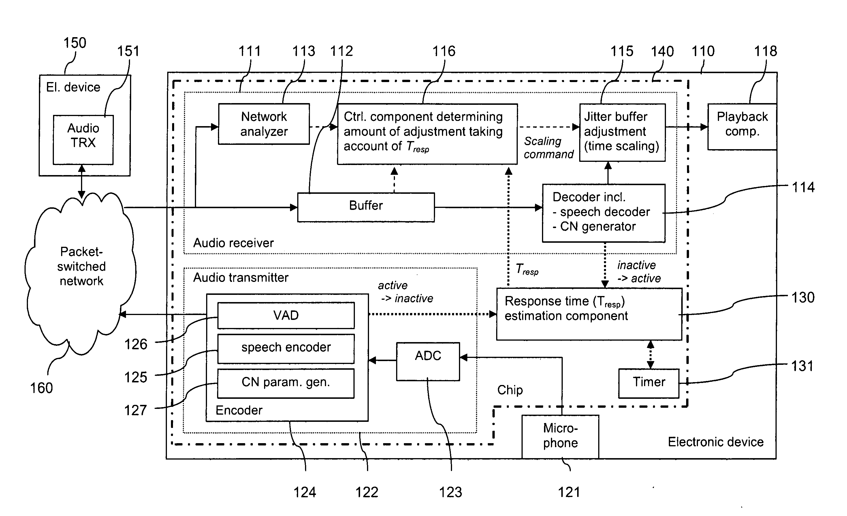
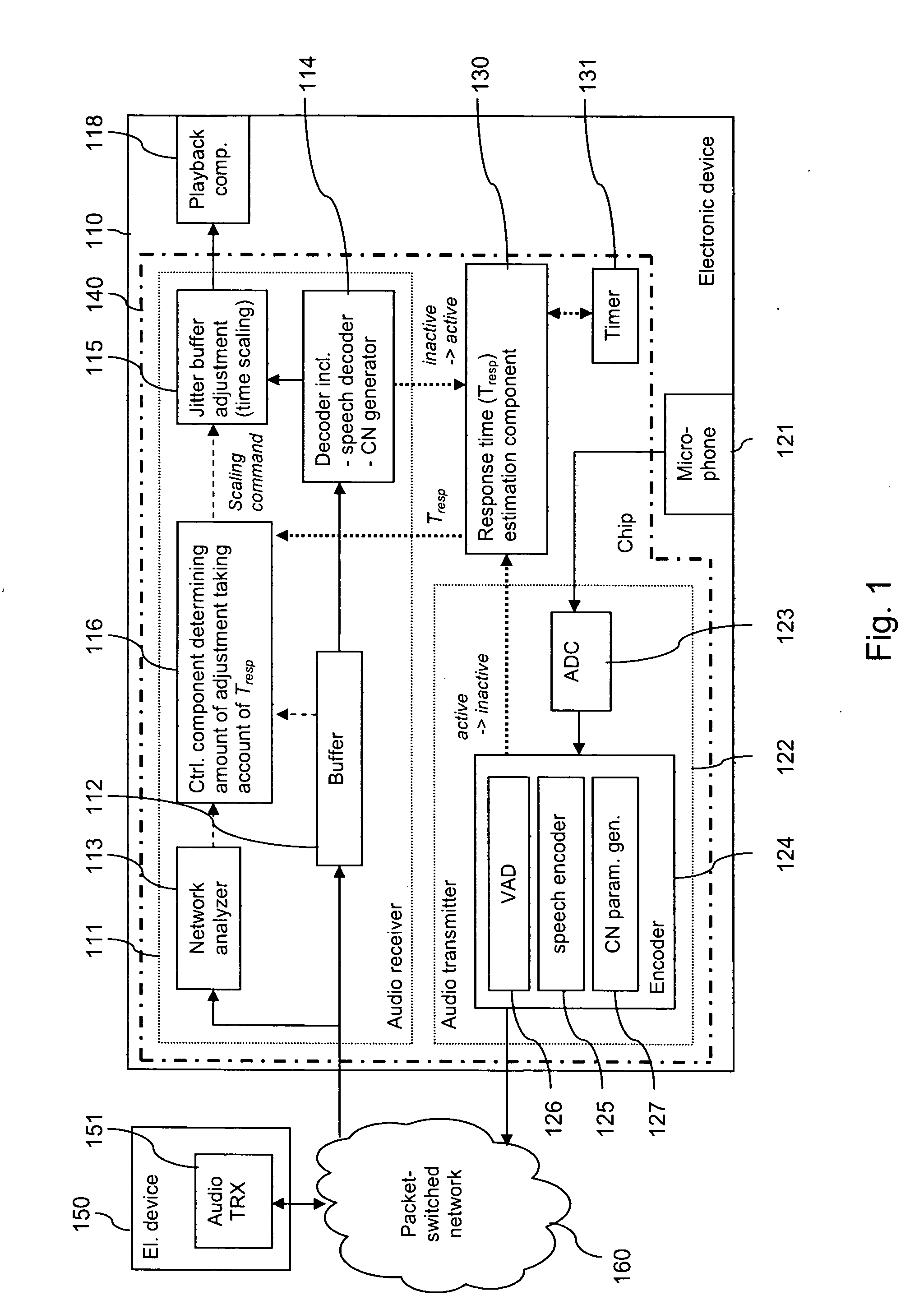
[0043]FIG. 1 is a schematic block diagram of an exemplary system, which enables an adjustment of an adaptive jitter buffering based on an estimated response time in accordance with an embodiment of the invention.

[0044]The system comprises a first electronic device 110, a second electronic device 150 and a packet switched communication network 160 interconnecting both devices 110, 150. The packet switched communication network 160 can be or comprise for example the Internet.

[0045]Electronic device 110 comprises an audio receiver 111, a playback component 118 linked to the output of the audio receiver 111, an audio transmitter 122, a microphone 121 linked to the input of the audio transmitter 122, and a response time (Tresp) estimation component 130, which is linked to both, audio receiver 111 and audio transmitter 122. The Tresp estimation component 130 is further connected to a timer 131. An interface of the device 110 to the packet switched communication network 160 (not shown) is ...


PUM


Abstract

For enhancing the performance of an adaptive jitter buffer, a desired amount of adjustment of a jitter buffer is determined at a first device using as a parameter an estimated delay. The delay comprises at least an end-to-end delay in at least one direction in a conversation. For this conversation, speech signals are transmitted in packets between the first device and a second device via a packet switched network. An adjustment of the jitter buffer is then performed based on the determined amount of adjustment.

Description

FIELD OF THE INVENTION[0001]The invention relates to a jitter buffer adjustment.BACKGROUND OF THE INVENTION[0002]For a transmission of voice, speech frames may be encoded at a transmitter, transmitted via a network, and decoded again at a receiver for presentation to a user.[0003]During periods when the transmitter has no active speech to transmit, the normal transmission of speech frames may be switched off. This is referred to as discontinuous transmission (DTX) mechanism. Discontinuous transmission saves transmission resources when there is no useful information to be transmitted. In a normal conversation, for instance, usually only one of the involved persons is talking at a time, implying that on an average, the signal in one direction contains active speech only during roughly 50% of the time. The transmitter may generate during these periods a set of comfort noise parameters describing the background noise that is present at the transmitter. These comfort noise parameters may...

Claims


Application Information

Patent Timeline
IPC IPC(8): H04J1/16H04L12/66H04L7/00H04J3/06H04L49/9023H04L47/30
CPCH04L43/087H04L47/10H04L49/90H04L47/283H04L47/22H04L49/9023
Inventor LAKANIEMI, ARI
Owner NOKIA TECHNOLOGLES OY
Why Eureka
Try Eureka