Film bulkacoustic wave resonator and method for manufacturing the same

Inactive Publication Date: 2008-02-28
PANASONIC CORP
View PDF6 Cites 31 Cited by
  • Summary
  • Abstract
  • Description
  • Claims
  • Application Information

AI Technical Summary

Benefits of technology

[0028]According to the film bulk acoustic wave resonator of the present invention as described above, the first mass load material portion has a laminated structure including: the first auxiliary electrode formed with the same material to have the same thickness as t

Problems solved by technology

In other words, in the case of forming a band-pass filter using a film bulk acoustic wave resonator, as in the above conventional examples, the problem also occurs that attenuation characteristics are degraded outside the pass band as shown in FIG. 19C, because each reso

Method used


Image

  • Film bulkacoustic wave resonator and method for manufacturing the same
  • Film bulkacoustic wave resonator and method for manufacturing the same
  • Film bulkacoustic wave resonator and method for manufacturing the same

Examples


first embodiment

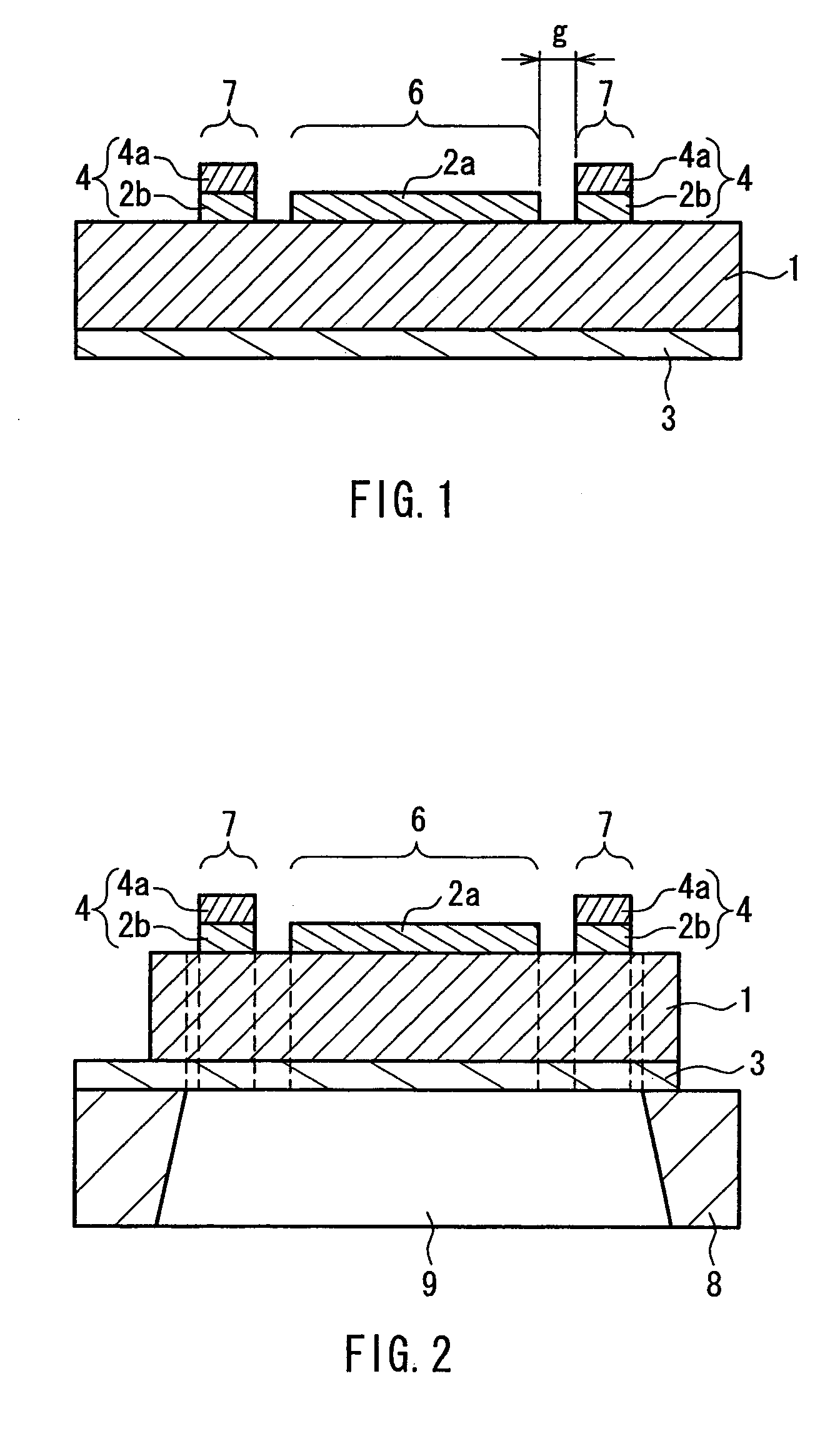
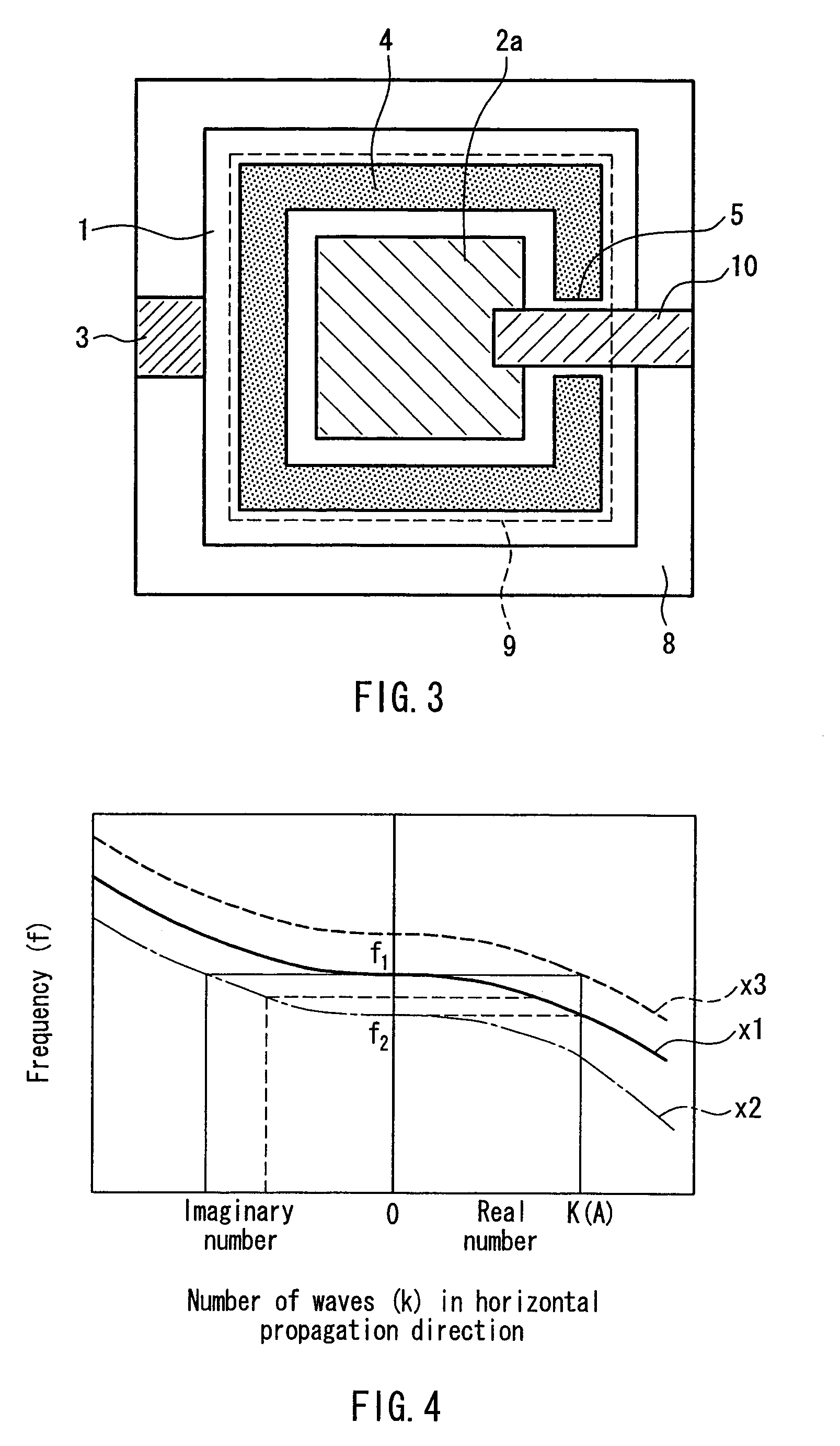
[0071]FIG. 1 is a cross sectional view showing an example of the structure of the resonance portion of the film bulk acoustic wave resonator according to a first embodiment of the present invention. FIG. 2 is a cross sectional view showing a film bulk acoustic wave resonator including a support structure for the resonance portion shown in FIG. 1. FIG. 3 is a top view showing an example of the structure in which wiring is included in the film bulk acoustic wave resonator of FIG. 2.

[0072]The film bulk acoustic wave resonator according to this embodiment has a resonance portion structure as shown in FIG. 1. Specifically, an upper electrode 2a is formed on a piezoelectric body 1, and a lower electrode 3 is formed under the piezoelectric body 1. A first mass load material portion 4 is formed so as to surround the upper electrode 2a on the piezoelectric body 1. The upper electrode 2a, the piezoelectric body 1 and the lower electrode 3 together form a center region 6. The first mass load m...

second embodiment

[0095]FIG. 6 is a cross sectional view showing an example of the structure of the resonance portion of a film bulk acoustic wave resonator according to a second embodiment of the present invention. The film bulk acoustic wave resonator according to this embodiment has a structure in which a lower electrode 3a, a piezoelectric body 1 and an upper electrode 2 are formed, in this order, on a substrate (not shown). The lower electrode 3a is formed only within a center region 6. A second mass load material portion 12 is formed outside of the lower electrode 3a between the substrate and the piezoelectric body 1. The lower electrode 3a, the piezoelectric body 1 and the upper electrode 2 together form the center region 6, and the second mass load material portion 12, the piezoelectric body 1 and the upper electrode 2 together form a mass load region 7. The outer periphery of the lower electrode 3a and the inner periphery of the second mass load material portion 12 are spaced apart from each...

third embodiment

[0108]FIG. 9 is a cross sectional view showing an example of the structure of the resonance portion of a film bulk acoustic wave resonator according to a third embodiment of the present invention. The film bulk acoustic wave resonator of this embodiment has a structure in which, in the film bulk acoustic wave resonator of the first embodiment shown in FIG. 1, the lower electrode 3 is divided at the boundary region between the center region 6 and the mass load region 7 so as to be patterned into a center lower electrode 3a and a second mass load material portion 3c.

[0109]In the structure of FIG. 1, strictly speaking, the electric field applied between the upper electrode 2a and the lower electrode 3 is not limited to the thickness direction. For this reason, when one of the upper electrode 2a and the lower electrode 3 is not divided, vibration in an oblique direction also may be generated, which contributes to the generation of different resonance modes.

[0110]In contrast, by providi...


PUM


Abstract

A film bulk acoustic wave resonator including a piezoelectric body 1, and a first electrode 2 and a second electrode 3 that are provided respectively on the main surfaces of the piezoelectric body, the piezoelectric body being applied an electric field through the first and the second electrodes so as to generate a resonant vibration. A first mass load material portion 4 having an annular shape is provided outside the planar region of the first electrode on the main surface of the piezoelectric body, a mass load effect thereof being larger than that of the first electrode. The outer periphery of the first electrode and the inner periphery of the first mass load material portion are spaced apart from each other, whereby the first electrode and the first mass load material portion are electrically insulated from each other. The first mass load material portion has a laminated structure including a first auxiliary electrode layer 2a and a load material layer 4a formed on the auxiliary electrode layer. The first auxiliary electrode is formed with the same material to have the same thickness as the first electrode. Energy loss can be reduced, while the first mass load material portion can be formed easily with high precision.

Description

BACKGROUND OF THE INVENTION[0001]1. Field of the Invention[0002]The present invention relates to a film bulk acoustic wave resonator configured to trap the energy of an acoustic wave in a resonance portion.[0003]2. Description of Related Art[0004]The components incorporated in electronic devices such as portable devices are demanded to be smaller and lighter. For example, filters used in portable devices are demanded to be smaller and to be capable of precise adjustment of frequency characteristics. As a filter that satisfies these demands, a filter having a film bulk acoustic wave resonator is known.[0005]A conventional film bulk acoustic wave resonator will be described below with reference to FIGS. 13, 14, 15A and 15B. FIG. 13 is a cross sectional view showing the basic structure of a conventional film bulk acoustic wave resonator 50. The film bulk acoustic wave resonator 50 has a resonance portion in which a piezoelectric body 51 is sandwiched between a lower electrode portion 5...

Claims


Application Information

Patent Timeline
IPC IPC(8): H04B1/38H03H9/00
CPCH03H9/173H03H9/174H03H9/605H03H9/177H03H9/564H03H9/175
Inventor IWASAKI, TOMOHIROONISHI, KEIJINAKATSUKA, HIROSHIYAMAKAWA, TAKEHIKOKAMIYAMA, TOMOHIDE
Owner PANASONIC CORP
Why Eureka
Try Eureka