Transmission power amplifier apparatus for combining power-amplified constant amplitude signals each having controlled constant amplitude value and phase

a technology of power amplifier and power amplifier, which is applied in the direction of rf amplifier, amplifier combination, transmission, etc., to achieve the effect of higher efficiency

Active Publication Date: 2008-02-28
GK BRIDGE 1
View PDF3 Cites 49 Cited by
  • Summary
  • Abstract
  • Description
  • Claims
  • Application Information

AI Technical Summary

Benefits of technology

[0038]Accordingly, the transmission power amplifier apparatus according to the present invention includes the signal calculator that divides the input signal into a plurality of N constant amplitude signals having the substantially same predetermined constant amplitude value and the different predetermined phases, detects the average value and one of the maximum value of the amplitude of the input signal and the peak-to-peak value thereof for the predetermined unit time interval, and decides the amplitude valu

Problems solved by technology

However, the LINC amplifier 10 according to the prior art has the following problems if, for example, the inputted modulated signal S(t) is a multi-valued digitally-modulated signal in which transmission information is superimposed on an amplitude component, and a dynamic r

Method used


Image

  • Transmission power amplifier apparatus for combining power-amplified constant amplitude signals each having controlled constant amplitude value and phase
  • Transmission power amplifier apparatus for combining power-amplified constant amplitude signals each having controlled constant amplitude value and phase
  • Transmission power amplifier apparatus for combining power-amplified constant amplitude signals each having controlled constant amplitude value and phase

Examples


first preferred embodiment

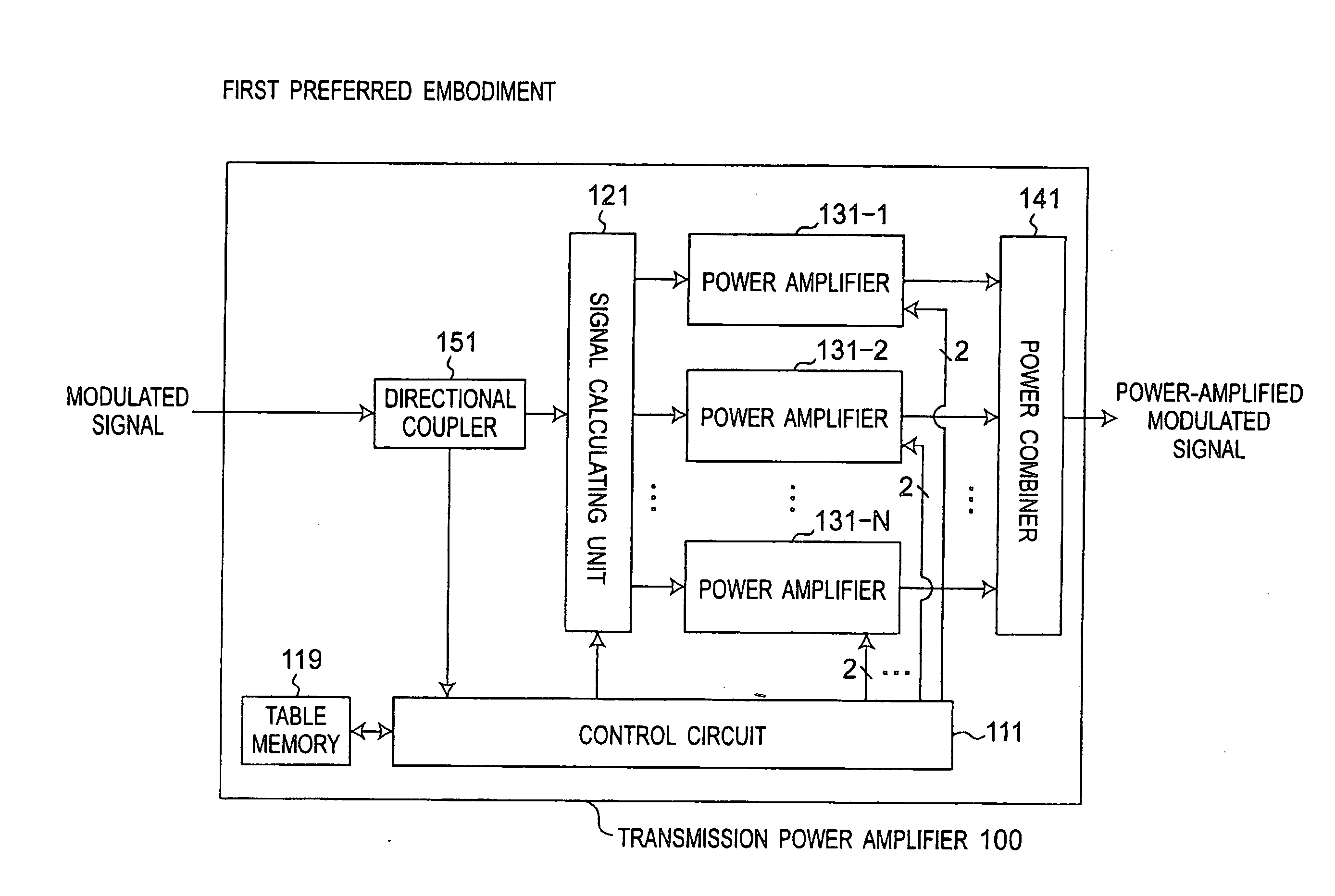
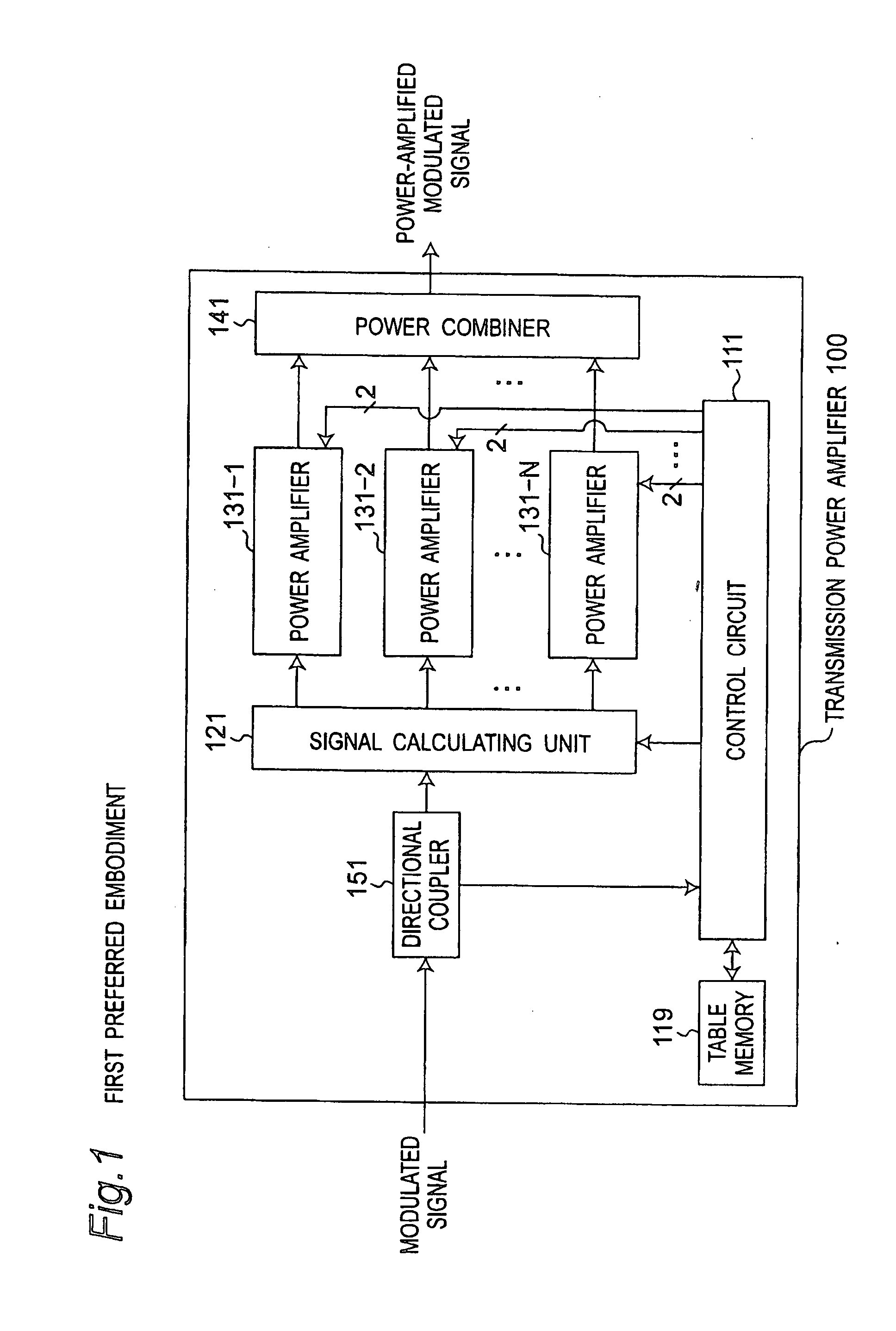
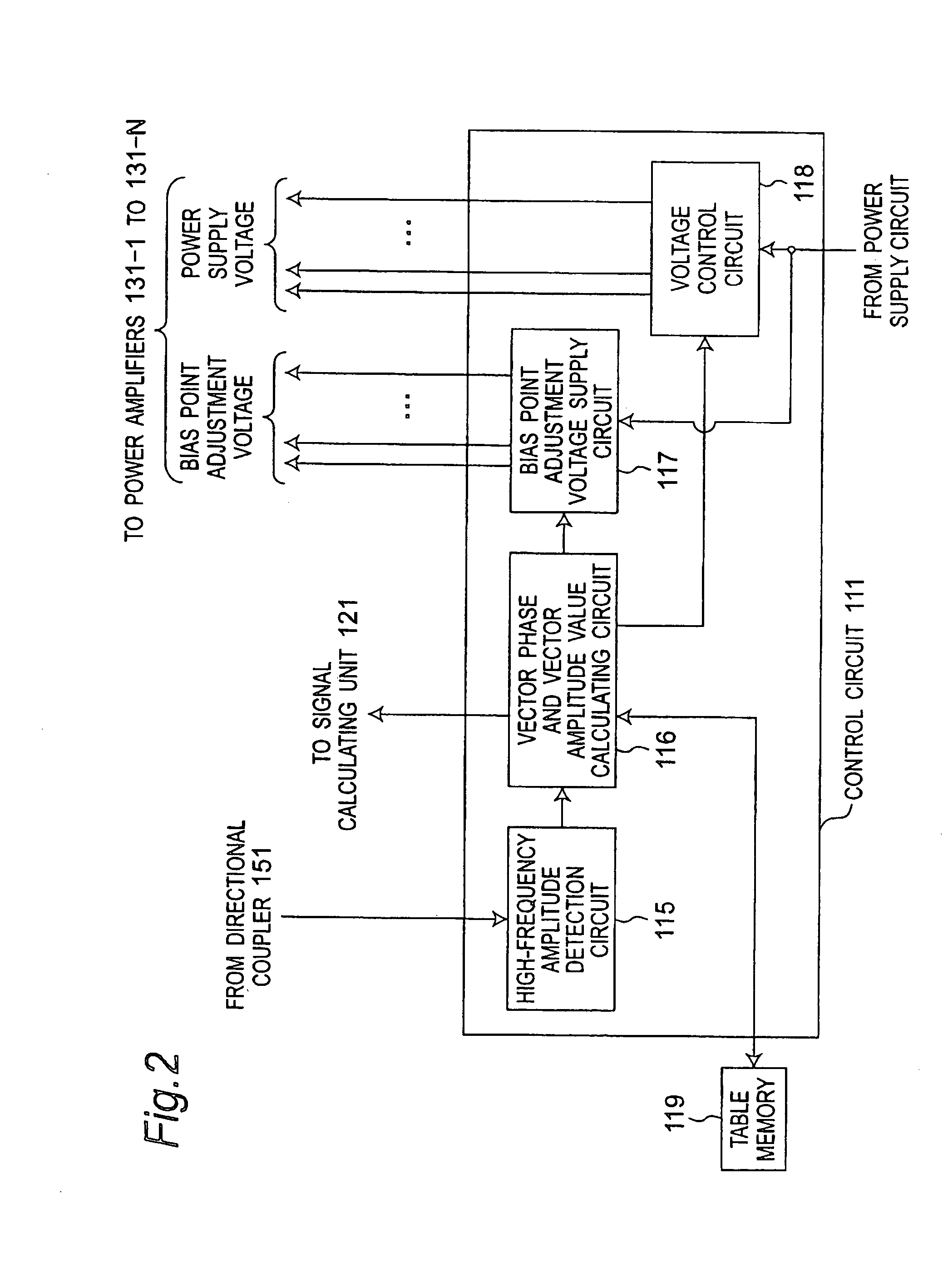
[0069]FIG. 1 is a block diagram showing a configuration of a transmission power amplifier apparatus 100 according to a first preferred embodiment of the present invention. FIG. 2 is a block diagram showing a configuration of a control circuit 111 shown in FIG. 1. FIG. 3 is a block diagram showing a configuration of a plurality of or N power amplifiers 131-n (where n=1, 2, . . . , N) shown in FIG. 1. Referring to FIG. 1, the transmission power amplifier apparatus 100 is characterized by including a directional coupler 151, a signal calculating unit 121, N power amplifiers 131-n, a power combiner 141, a control circuit 111, and a table memory 119. Referring to FIG. 2, the control circuit 111 is configured to include a high-frequency amplitude detection circuit 115, a vector phase and vector amplitude value calculating circuit 116, a bias point adjustment voltage supply circuit 117, and a voltage control circuit 118. Referring to FIG. 3, each of the N power amplifiers 131-n is configur...

second preferred embodiment

[0127]FIG. 17 is a block diagram showing a configuration of a transmission power amplifier apparatus 100c according to a second preferred embodiment of the present invention. FIG. 18 is a block diagram showing a configuration of a control circuit 111c shown in FIG. 17. The transmission power amplifier apparatus 100c according to the second preferred embodiment is characterized, as compared with the transmission power amplifier apparatus 100 according to the first preferred embodiment, by including a control circuit 111c in place of the control circuit 111 and a digital modulator 161 that receives I and Q signals orthogonal to each other in place of the directional coupler 151. The digital modulator 161 low-pass-filters the received I and Q signals, outputs the low-pass-filtered I and Q signals to the control circuit 111c, converts the low-pass-filtered I and Q signals into a digitally modulated signal in which each of a phase component and an amplitude component contains transmissio...

third preferred embodiment

[0131]FIG. 19 is a block diagram showing a configuration of a transmission power amplifier apparatus 100d according to a third preferred embodiment of the present invention. FIG. 20 is a block diagram showing a configuration of a control circuit 111d shown in FIG. 19. The transmission power amplifier apparatus 100d according to the third preferred embodiment is characterized, as compared with the transmission power amplifier apparatus 100c according to the second preferred embodiment, by including a control circuit 111d in place of the control circuit 111c and further including a baseband circuit 171. The baseband circuit 171 receives transmission data, generates I and Q signals orthogonal to each other based on the received transmission data, outputs the I and Q signals to a digital modulator 161, and outputs digital data used to generate the I and Q signals to the control circuit 111d. The differences of the third preferred embodiment from the second preferred embodiment will be d...


PUM


Abstract

In a transmission power amplifier apparatus, a signal calculator divides an input signal into a plurality of N constant amplitude signals having a substantially identical predetermined constant amplitude value and having predetermined phases different from each other, and N power amplifiers amplify electric powers of the N constant amplitude signals under same predetermined operating condition. A power combiner combines the electric powers of the N power-amplified constant amplitude signals, and outputs a combined output signal. A controller controls the signal calculator to detect an amplitude value of the input signal, to detect an average value and one of a maximum value of the amplitude value of the input signal and a peak-to-peak value of the amplitude value for a unit time interval based on the detected amplitude value of the input signal, and to divide the input signal into the N constant amplitude signals having a constant amplitude value and different phases.

Description

FIELD OF THE INVENTION[0001]The present invention relates to a transmission power amplifier apparatus provided in, for example, a radio communication apparatus and power amplifying an inputted radio transmission signal, a method of controlling the transmission power amplifier apparatus, and a radio communication apparatus using the transmission power amplifier apparatus.BACKGROUND OF THE INVENTION[0002]In recent years, it has been required to communicate a large capacity of data at high speed in a radio communication, and demand for transmitting a multi-valued digitally-modulated signal rises accordingly. Generally speaking, transmission information is superimposed not only on a phase component but also on an amplitude component in the multi-valued digitally-modulated signal. Due to this, a radio transmitter apparatus transmitting the multi-valued digitally-modulated signal is required to have a quite high linearity. On the other hand, as portable radio communication apparatuses typ...

Claims


Application Information

Patent Timeline
IPC IPC(8): H01Q11/12H03F3/04H03F3/68
CPCH03F1/0211H03F1/0261H03F1/0277H03F1/0294H03F2200/451H03F3/24H03F3/68H03F2200/336H03F3/211
Inventor TAKEHARA, HIROYASU
Owner GK BRIDGE 1
Why Eureka
Try Eureka