Tube, stent and collar insertion device

Inactive Publication Date: 2008-02-28
UNIV OF VIRGINIA ALUMNI PATENTS FOUND
View PDF10 Cites 195 Cited by
  • Summary
  • Abstract
  • Description
  • Claims
  • Application Information

AI Technical Summary

Benefits of technology

[0031] In other aspects, the invention includes a device which is exceptionally streamlined and facilitates a clear line of sight for the surgeon to view the incision in the tympanic membrane without unnecessary obstruction by the device.
[0032] In another aspect, the invention includes a device which allows the surgeon to “feel” the insertion of the PE tube by letting the surgeon apply the amount of pressure/force he/she desires when inserting the tube into the incision, thus allowing him/her complete control over the insertion event.
[0033] Some aspects of various embodiments of the present invention provide

Problems solved by technology

Fluid in the middle ear space puts pressure on the tympanic membrane and can cause pain, hearing loss, speech and language delays, and structural damage to the tympanic membrane and other structures vital to the processing of sound information.
The number of instruments and instrument passes through the ear drum takes time and creates risk.
However even this approach was unsatisfactory because, but not limited thereto, the proprietary PE tube could only be used at particular loc

Method used


Image

  • Tube, stent and collar insertion device
  • Tube, stent and collar insertion device
  • Tube, stent and collar insertion device

Examples


example 1

Reusable Device

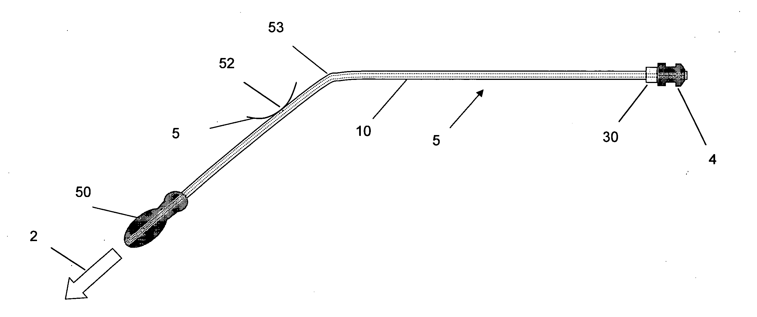
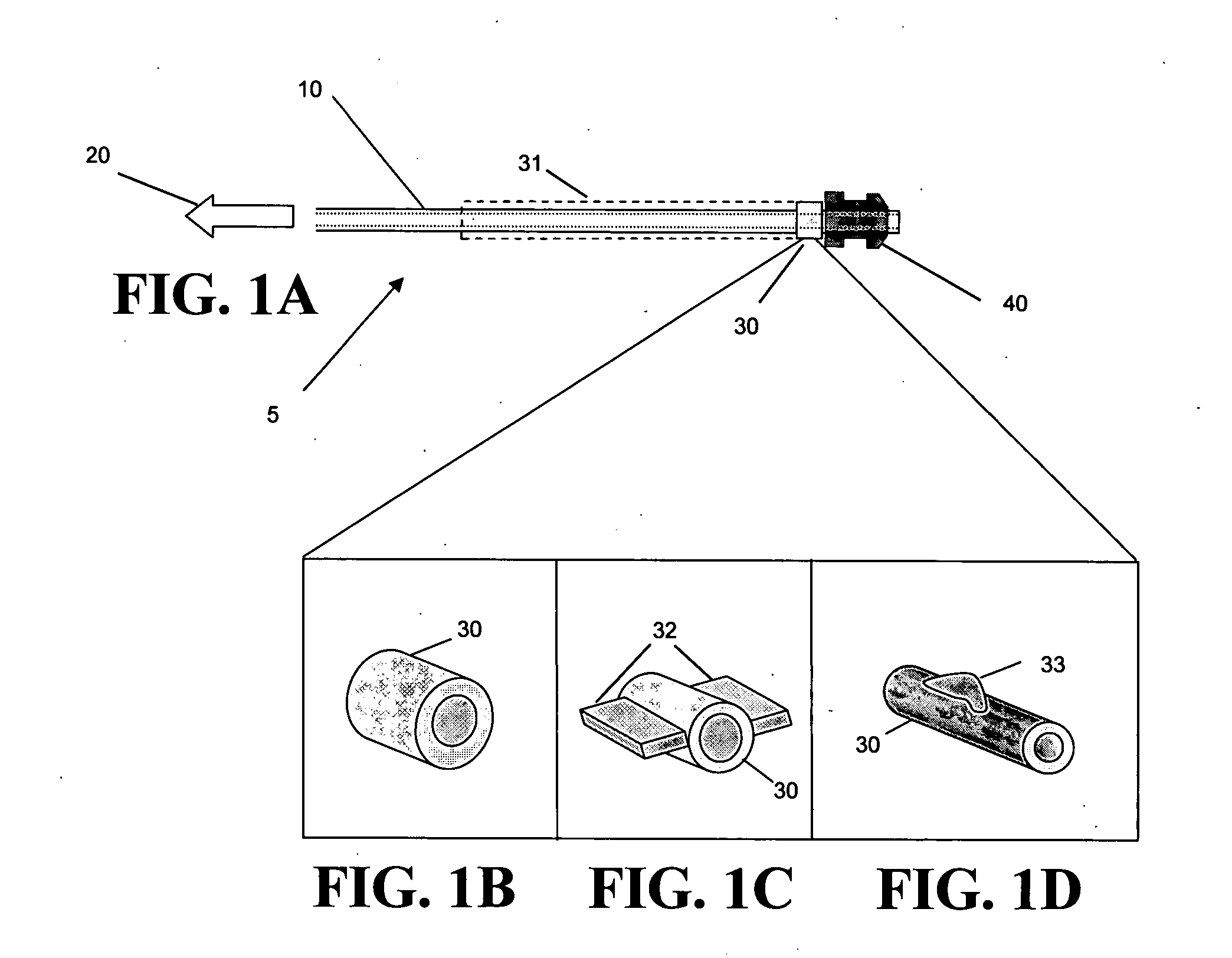
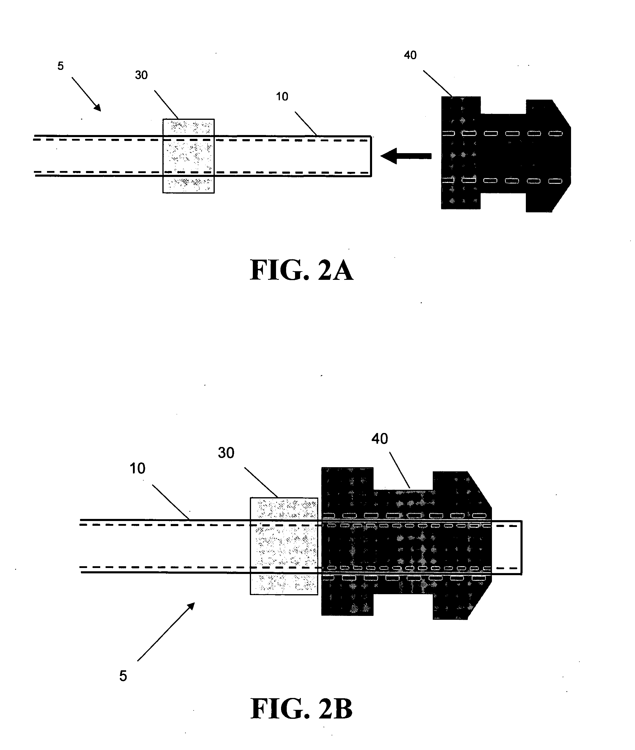
[0083]FIG. 7 depicts an exemplary device that may be reusable and made out of stainless steel (or any material as desired), much like the existing suctioning device, so that it can be autoclaved between uses. It should be appreciated that the device may be made of materials that lend itself to be disposable. It may look and feel similar to the existing suction device. It consists of a thin tube 10 (o.d. ranging from 0.86 mm to 1.5 mm, and wall thickness varying accordingly) with a slight angle 53 (approximately 45 deg.) approximately ⅓ of the way from the proximal end of the tube—note that the “proximal end” is defined as the end or region of the tube / device that hooks into the wall suction; the “distal end” is defined as the end or region that bears the ear tube 40 and is inserted into the ear drum. At the proximal end of the tube is a hub connector 50 for a vacuum wall tube.

[0084] However, among other things, it contains a collar 30 strategically located near the ...

example 2

Disposable Device

[0090] This exemplary disposable device has same shape and form as the reusable device described above. It also comes in 3 different sizes (or as different as desired). A difference is that it is made out of a cheaper, disposable material (similar to that of disposable needles, or perhaps strong plastic). The disposable device comes pre-packaged in a sterile pack with the PE tube pre-loaded on the tip of the device. The surgeon simply opens the sterile pack, removes the device (containing the PE tube), hooks the distal end of the device into the wall vacuum unit, and places the PE tube into the incision using the device. After the procedure, the disposable insertion device is discarded.

example 3

Incorporation of Myringotomy Blade

[0091]FIG. 8 represents the surgical device 5 incorporating a blade which may be retracted by the user. The cutting blade 60 is mounted on a rod (‘blade rod’) 61. The blade rod runs inside the rod 10, and is supported by the ‘support shelf’62. The end of the blade rod is connected to the ‘slide tab’63, near the thumb rest 51. The slide tab protrudes through a slit 64 from the rod 10. The slide tab can move forward and backward. When the slide tab is in the forward position, the blade protrudes from the end of the suction tube. When the slide tab is in the backward position, the blade is not exposed. As with any of the embodiments or examples discussed throughout it may be disposable or reusable or combination thereof, as well as pre-packed and / or pre-loaded.


PUM


Abstract

A surgical device and method designed to make insertion of pressure equalization tubes for effusion of the inner ear faster, more reliable, and safer by combining the placement of the pressure equalization tube with suction of the inner ear, decreasing the number of instruments and instrument passes into and out of the ear canal. A surgical insertion tool permits the direct coaxial insertion of the stent through the surgically created ostium, and which may be under direct, clear endoscopic control.

Description

RELATED APPLICATIONS [0001] This application is a continuation-in-part of PCT International application No. serial No. PCT / US2006 / 17906, filed May 5, 2006, entitled, “Surgical Tool and Insertion Device for Tube Placement,” which claims benefit of priority from U.S. Provisional Application Ser. No. 60 / 677,902, filed May 5, 2005, entitled “Surgical Tool and Inserter Device for Tube-Placement Solution During Myringotomy,” of which the disclosures are hereby incorporated by reference herein in their entirety. Additionally, the present patent application claims benefit of priority from U.S. Provisional Application Ser. No. 60 / 846,072, filed Sep. 20, 2006, entitled “Pressure Equalization (PE) Tube Insertion Device and Collar Suction Adaptation and Related Method,” and U.S. Provisional Application Ser. No. 60 / 850,669, filed Oct. 10, 2006, entitled “Sinus Stent Insertion Device and Related Method,” of which the disclosures are hereby incorporated by reference herein in their entirety.FIELD ...

Claims


Application Information

Patent Timeline
IPC IPC(8): A61F11/00
CPCA61F11/002A61F11/202
Inventor COTTLER, SHAYN PEIRCEKESSER, BRADLEY W.
Owner UNIV OF VIRGINIA ALUMNI PATENTS FOUND
Why Eureka
Try Eureka