Method of Real Time-Estimation of Indicators of the Combustion State of an Internal-Combustion Engine

Inactive Publication Date: 2008-02-28
INST FR DU PETROLE
View PDF14 Cites 32 Cited by
  • Summary
  • Abstract
  • Description
  • Claims
  • Application Information

AI Technical Summary

Problems solved by technology

This method allows to directly access physical indicators of the combustion but, because of the life and cost of this type of detectors, they cannot be standard yet in vehicles.
Extraction of coherent combustion state indicators from an accelerometer is d

Method used


Image

  • Method of Real Time-Estimation of Indicators of the Combustion State of an Internal-Combustion Engine
  • Method of Real Time-Estimation of Indicators of the Combustion State of an Internal-Combustion Engine
  • Method of Real Time-Estimation of Indicators of the Combustion State of an Internal-Combustion Engine

Examples


application example

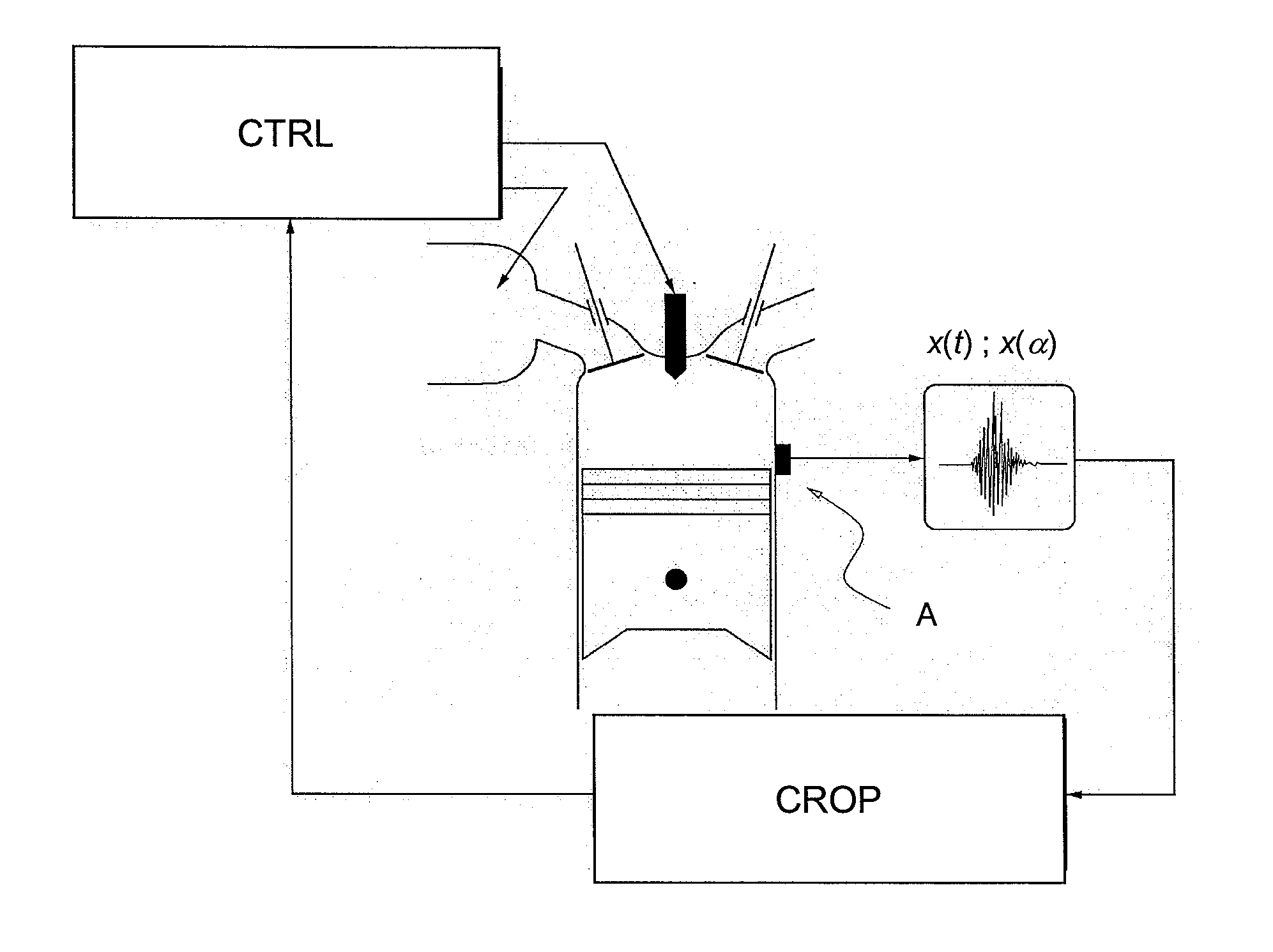
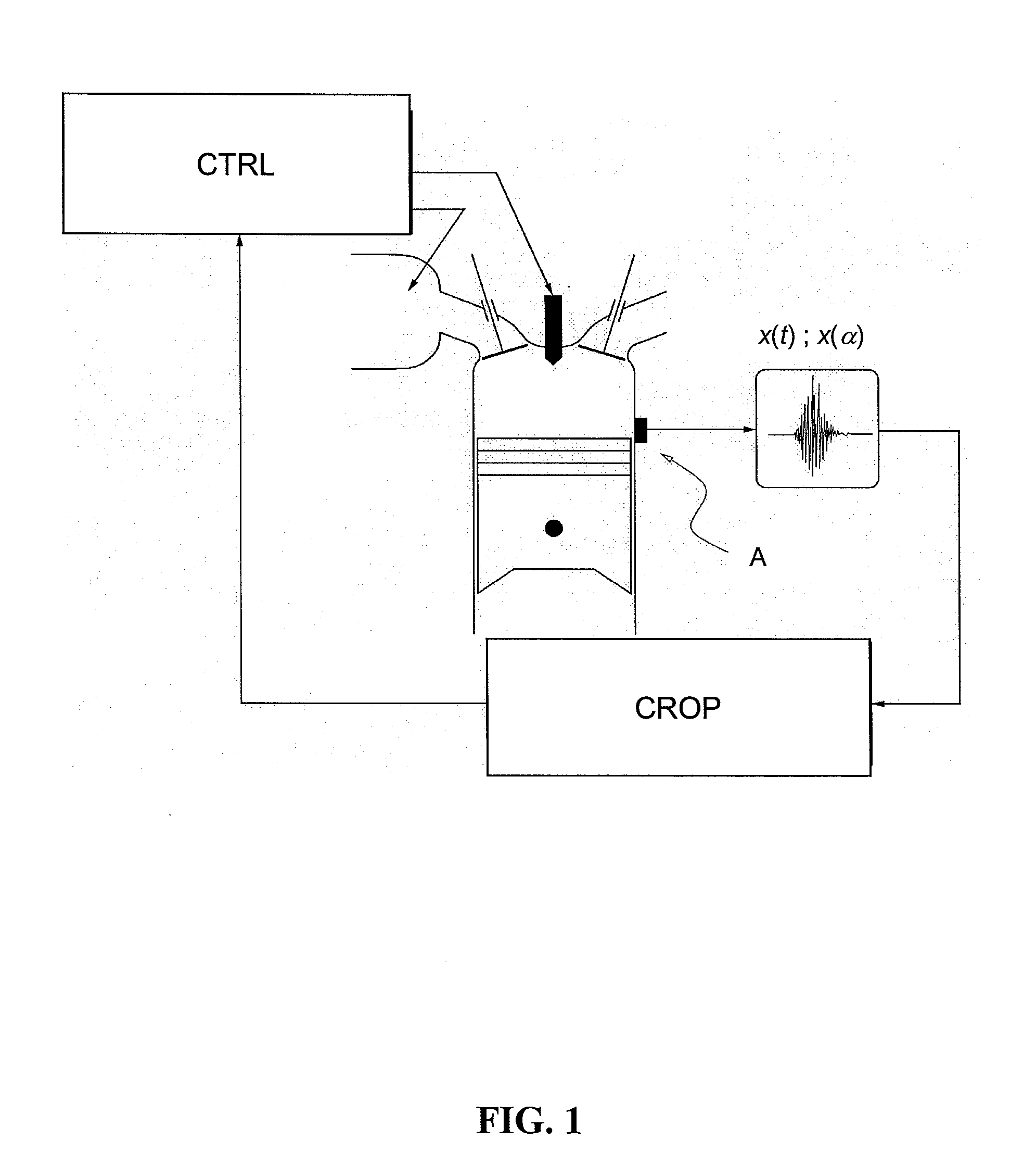
[0122] A straight four-cylinder engine was equipped with an accelerometric detector positioned on the engine block. A platform allows on-line data acquisition and processing.

[0123] Determination of the Frequency Band of Interest

[0124] The frequency band associated with the combustion phenomenon is determined between 0 and 2 kHz by means of a time-frequency analysis.

[0125] Methodology Application and Results

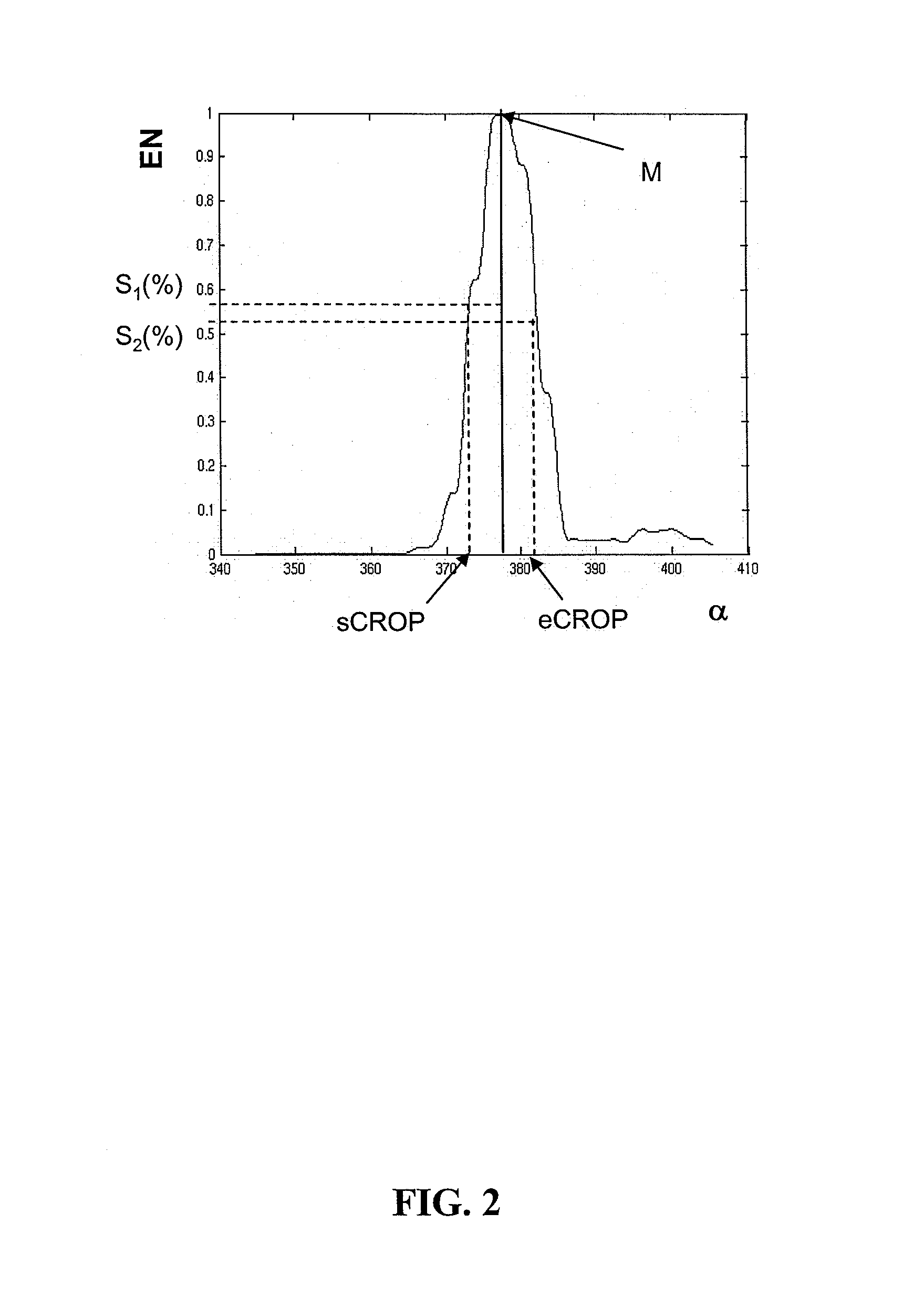
[0126] The methodology is applied using the following parameters:

ParametersValuesFilter cutoff frequencies0 and 2.5 kHzNumber of samples N of the48 pointsanalysis windowDiscrete frequencies considered k1sCROP extraction threshold10%eCROP extraction threshold10%

[0127] In order to ascertain the validity of the indicators extracted from the accelerometric signal, the methodology has also been applied to the cylinder pressure signal, considered to be the reference signal by experts. FIG. 3 shows the indicators obtained from the pressure signal (full line) and from the accelerome...


PUM


Abstract

A method of real-time estimation of indicators of the engine combustion state from signals containing oscillating components. A signal, such as a vibration signal for example, correlated with the engine combustion, is acquired as a function of time or of the crank angle. Real-time filtering and time-frequency analysis of this signal is carried out and indicators of the combustion state are estimated in real time from this analysis. The method has application for combustion control of an internal-combustion engine.

Description

FIELD OF THE INVENTION [0001] The present invention relates to a method of real-time estimation of indicators of the combustion state of an internal-combustion engine equipped with one or more detectors. [0002] According to the invention, estimation of combustion state indicators can be used within the context of combustion control of an internal-combustion engine by modifying the engine parameters depending on the evolution of the indicators obtained with this method. [0003] Emissions reduction standards have led to a progressive adaptation of engine technologies such as the introduction of additional actuators (exhaust gas recirculation valve, direct electronic injection, variable-geometry turbine) and new combustion modes (homogeneous diesel combustion or stratified gasoline combustion). In this context, the engine has become an assembly of complex systems requiring management by means of modern automation techniques. The engine control function consists in managing the available...

Claims


Application Information

Patent Timeline
IPC IPC(8): F02D28/00
CPCF02D35/02F02D35/021F02D35/023F02D35/028F02D41/1498F02D41/2467F02D2041/288F02D2200/025G01L23/225G01M15/12F02D41/2438F02D2041/1432
Inventor KER, STEPHANDUVAL, LAURENT
Owner INST FR DU PETROLE
Why Eureka
Try Eureka