Eureka AIR delivers breakthrough ideas for toughest innovation challenges, trusted by R&D personnel around the world.

Engine noise reduction apparatus

Active Publication Date: 2008-03-06
CATERPILLAR INC
View PDF25 Cites 7 Cited by
  • Summary
  • Abstract
  • Description
  • Claims
  • Application Information

AI Technical Summary

Benefits of technology

[0010]In another aspect, a method of reducing engine noise on a vehicle is disclosed. The method includes providing an internal combustion engine supported on a vehicle and substantially enclosing the engine in an enclosure, providing a separator wall within the enclosure, the se

Problems solved by technology

The subject of noise pollution has become a critical issue in recent years and has had a very significant impact on the earthmoving industry.
Obviously, one of the primary sources of noise emanates from the engine of the vehicle.
However, as the noise requirements have become more stringent, problems with this method of noise attenuation have been encountered.
Not only is the flow of air that is passed by the fluid cooling devices reduced, but the flow of air through the enclosure itself is reduced which results in an overall increase in temperature within the compartment.
This adversely affects many temperature sensitive components, such as the alternator, the fuel injection system and various electronic components such as microprocessors that have been incorporated into the operation of an engine through modern day engine technology.
While this solution has achieved moderate success, conditions have reached a point where the fan speed requirements are so great that the noise created by the fan has surpassed the engine as the dominant noise source, particularly at high idle with an engine driven fan.
This requires relatively large openings in the engine compartment, however, to provide adequate air flow; and thus, highly efficient noise attenuation is sacrificed.
Also, the flow of air is not controllable and is only effective while the engine is running.
With a tightly sealed, sound suppressed engine enclosure, the temperature rise experienced within the enclosure after engine shut down can result in premature failure of temperature sensitive components such as microprocessors.
Additionally, since a fan is a volumetric flow device and the airflow through the conduit enters the fan inlet air stream, the fan speed must be increased above that speed sufficient to satisfy the fluid cooling device airflow requirements, thereby resulting in a fan noise penalty.

Method used


Image

  • Engine noise reduction apparatus
  • Engine noise reduction apparatus
  • Engine noise reduction apparatus

Examples


Embodiment Construction

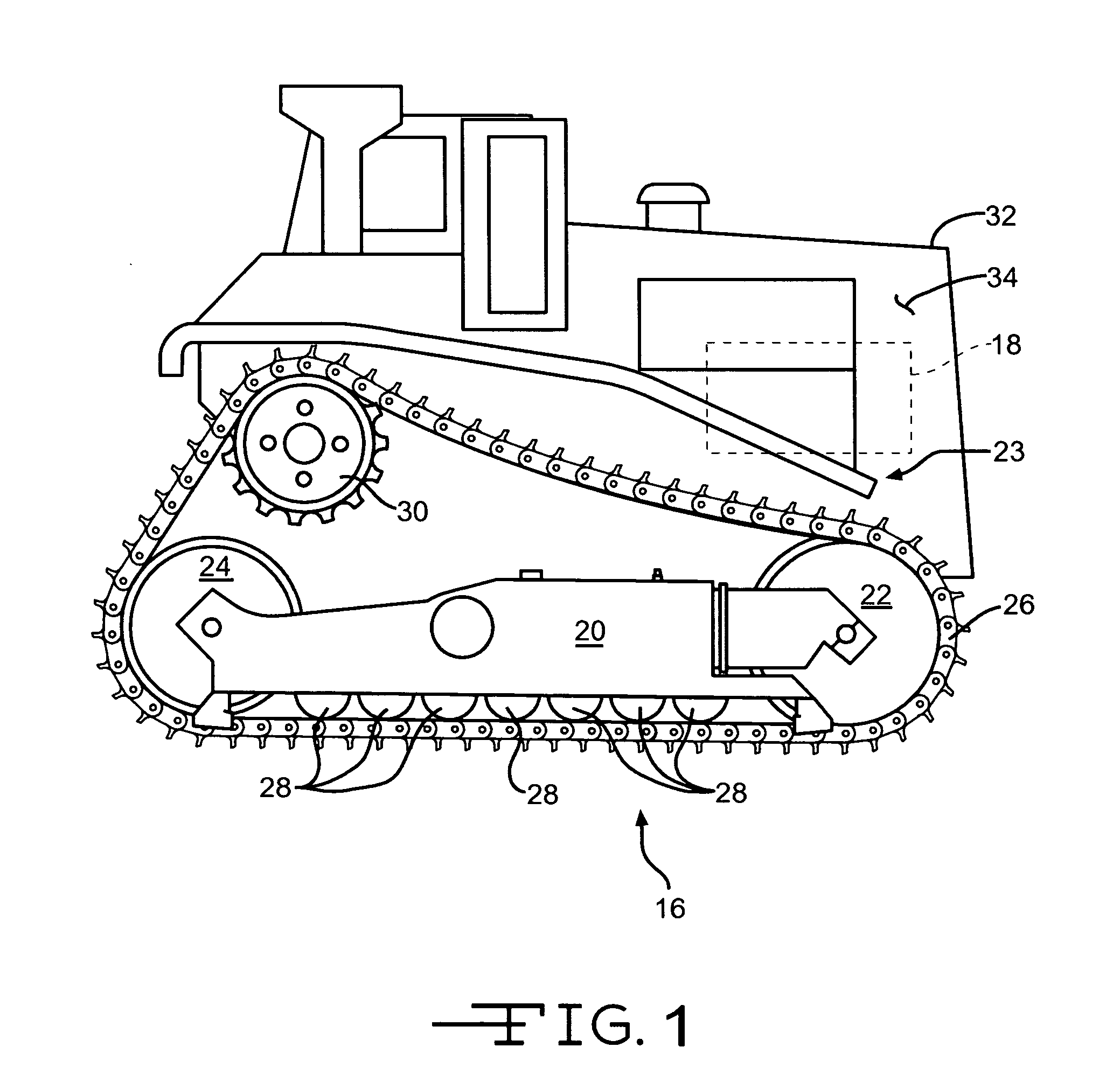
[0017]Referring to FIG. 1, a vehicle 10 such as a track type tractor 12 is illustrated. The track type tractor 12 includes a frame shown generally as 14 and an engine 18 (shown schematically) mounted on the frame 14. The engine 18 drivingly engages a powertrain or drivetrain that is coupled to an undercarriage assembly 16, for propelling the machine about the ground. The undercarriage assembly 16 including a right side, seen in FIG. 1, and a left side (not shown) is attached to the frame 14. The undercarriage assembly 16 includes a frame rail 20 having a front idler 22 and a rear idler 24 mounted thereupon. Pluralities of bogie wheels 28 are positioned below the frame rail 20 to support the machine on the track assembly 26. A drive sprocket 30 is positioned above the undercarriage assembly 16 and is drivingly coupled to the engine 18. The track assembly 26 encompasses the undercarriage assembly 16 and engages the drive sprocket 30, front idler 22, rear idler 24, and bogie wheels 28....


PUM

PropertyMeasurementUnit
Electrical resistanceaaaaaaaaaa

Abstract

A vehicle including an enclosure and a separator wall is disclosed. The enclosure defines an engine compartment and the engine compartment encloses an internal combustion engine. The separator wall extends from a forward portion of the engine compartment to a rear portion of the engine compartment. The engine compartment is at least partially separated into an upper portion and a lower portion by the separator wall.

Description

TECHNICAL FIELD[0001]The present disclosure relates generally to an engine noise reduction apparatus and more particularly to a partial enclosure resulting in improved noise restriction.BACKGROUND[0002]The subject of noise pollution has become a critical issue in recent years and has had a very significant impact on the earthmoving industry. Rigid sound requirements for equipment have been adopted worldwide, resulting in extensive modifications to vehicles in an attempt to reduce the noise produced during their operation. Obviously, one of the primary sources of noise emanates from the engine of the vehicle. The most logical way to reduce the noise is to encase the engine in an enclosure that is lined with acoustical foam or other sound absorptive material. While this solution appears simple enough, one must remain aware of the cooling requirements for the engine and other powertrain components such as torque converters, hydraulic pumps, etc., whose heat exchangers are cooled by air...

Claims


Application Information

Patent Timeline
IPC IPC(8): B01D46/00
CPCB60R13/0838
Inventor REDMANN, MICHAEL A.
Owner CATERPILLAR INC
Why Eureka
Eureka Blog
Learn More