Combustion control based on a signal from an engine vibration sensor
- Summary
- Abstract
- Description
- Claims
- Application Information
AI Technical Summary
Benefits of technology
Problems solved by technology
Method used
Image
Examples
Embodiment Construction
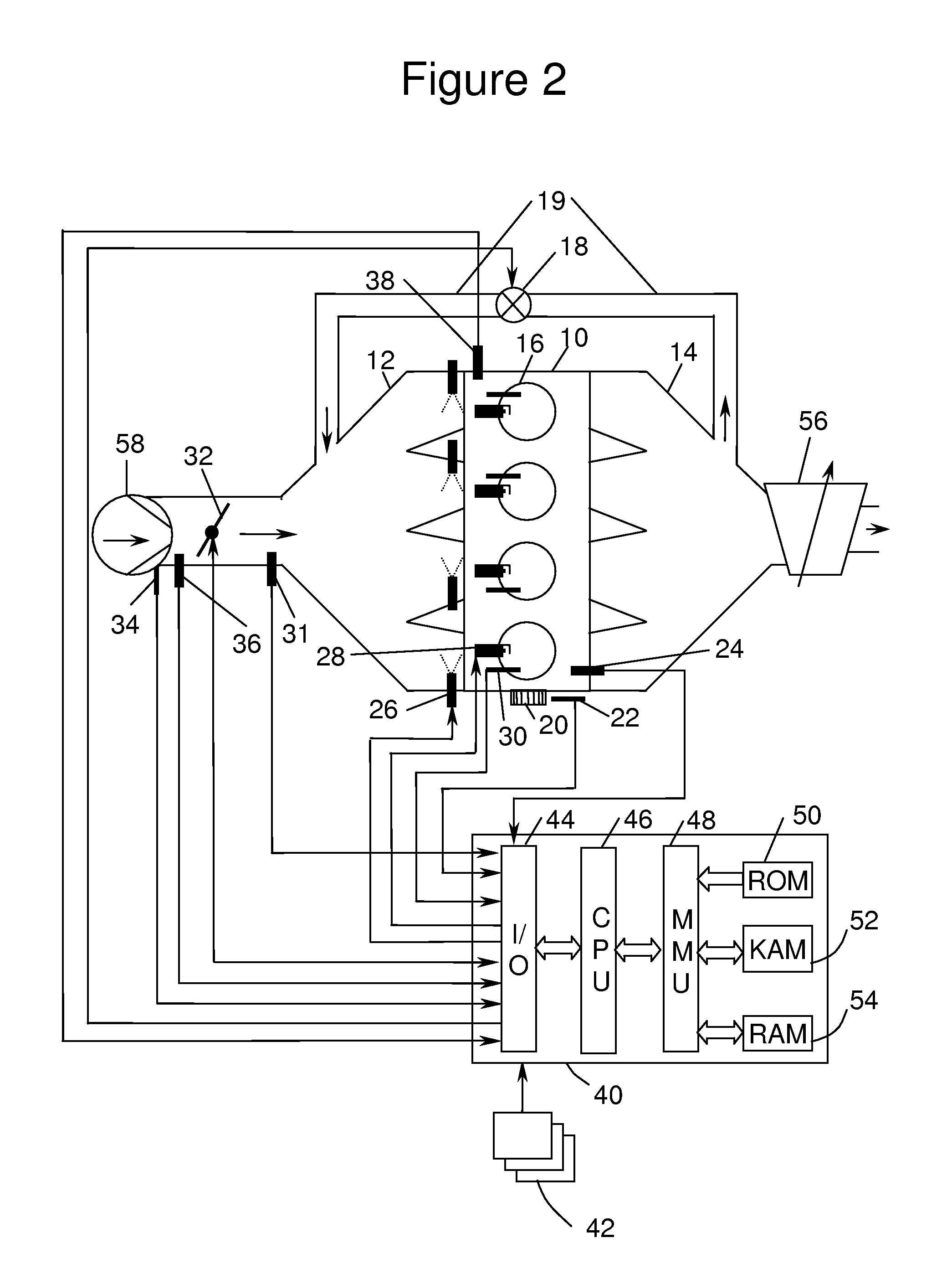
[0027]A 4-cylinder internal combustion engine 10 is shown, by way of example, in FIG. 2. Engine 10 is supplied air through intake manifold 12 and discharges spent gases through exhaust manifold 14. An intake duct upstream of the intake manifold 12 contains a throttle valve 32 which, when actuated, controls the amount of airflow to engine 10. Sensors 34 and 36 installed in intake manifold 12 measure air temperature and mass air flow (MAF), respectively. Sensor 31, located in intake manifold 14 downstream of throttle valve 32, is a manifold absolute pressure (MAP) sensor. A partially closed throttle valve 32 causes a pressure depression in intake manifold 12 compared to the pressure on the upstream side of throttle valve 32. When a pressure depression exists in intake manifold 12, exhaust gases are caused to flow through exhaust gas recirculation (EGR) duct 19, which connects exhaust manifold 14 to intake manifold 12. Within EGR duct 19 is EGR valve 18, which is actuated to control EG...
PUM
 Abstract
Description
Claims
Application Information
 - R&D
- Intellectual Property
- Life Sciences
- Materials
- Tech Scout
- Unparalleled Data Quality
- Higher Quality Content
- 60% Fewer Hallucinations
Browse by: Latest US Patents, China's latest patents, Technical Efficacy Thesaurus, Application Domain, Technology Topic, Popular Technical Reports.
© 2025 PatSnap. All rights reserved.Legal|Privacy policy|Modern Slavery Act Transparency Statement|Sitemap|About US| Contact US: help@patsnap.com


