Coat-stripping unit and method for its operation

a coating stripping and unit technology, applied in the field of coating stripping units, can solve the problems of shortening the life of the coating, unable to avoid the residue, and affecting the quality of the coating, and achieve the effects of reducing the cost of the coating

Active Publication Date: 2008-03-06
OERLIKON SURFACE SOLUTIONS AG PFAFFIKON
View PDF10 Cites 12 Cited by
  • Summary
  • Abstract
  • Description
  • Claims
  • Application Information

AI Technical Summary

Benefits of technology

[0005]It is the object of the invention further to develop coat-stripping units of the generic type so that the process of coat stripping is substantially simplified and can be carried out with great reliability. This object is achieved by the features in the characterizing clause of claim 1. In addition, methods for operating a coat-stripping unit according to the invention are described, by means of which coat stripping and also, in addition to the coat stripping, more complex processes comprising further steps can be carried out in a simple manner.
[0006]Advantages of the invention are in particular that stripping the coat from workpiece supports can be effected substantially more easily and more gently. Since mechanical processing can be substantially avoided, the life is substantially longer. After treatment is necessary at most to a small extent (washing, spraying, drying) and requires scarcely any manual work. In addition, however, stripping the coat from worn and incorrectly coated workpieces is also substantially simplified and can be effected far more reliably. By turning the workpiece support, a more or less uniform current density—averaged over the processing time—can be achieved more easily. Particularly in the case of workpieces having a non-conductive coating, the handling is generally substantially simplified since the workpieces are contacted in exactly the same way as in the case of the coating during the coat stripping.
[0007]Particularly if incorrectly coated workpieces are to be stripped of the coat and recoated, the handling effort can be substantially reduced if the workpieces are processed by means according to the invention. For coat stripping, they remain in this case on the workpiece support on which they were originally coated. Removal and remounting are dispensed with since the workpiece support with the mounted and contacted workpieces is transferred from a coating unit to the coat-stripping unit according to the invention and inserted therein. In the case of recoating of the workpieces, the workpiece support with the workpieces is transferred in the same way after coat stripping to a coating unit and inserted therein, whereupon the workpieces are recoated. Direct handling of the workpieces can be dispensed with.

Problems solved by technology

Nevertheless, frequently residues cannot be avoided, which may subsequently lead to malfunctions.
Moreover, the workpiece supports are unevenly worn during the sand blasting and are subject to considerable wear, which shortens their life.
This is particularly complicated in the removal of layers of non-conductive material where the contacting is subject to further limitations and the workpieces have to be mounted individually on holders.
The formation and positioning of the opposite electrode surface in known coat-stripping units of the generic type are difficult and cannot always be optimally realised, since the current flow should be distributed as uniformly as possible over those surface regions of the workpieces from which the coat is to be stripped, so that uniform coat stripping is achieved and corrosion of the body bearing the coating is avoided.

Method used


Image

  • Coat-stripping unit and method for its operation
  • Coat-stripping unit and method for its operation

Examples


Embodiment Construction

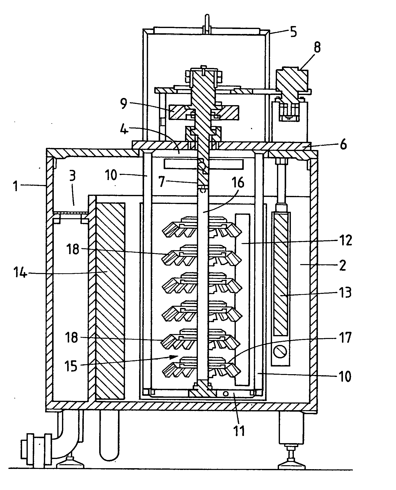
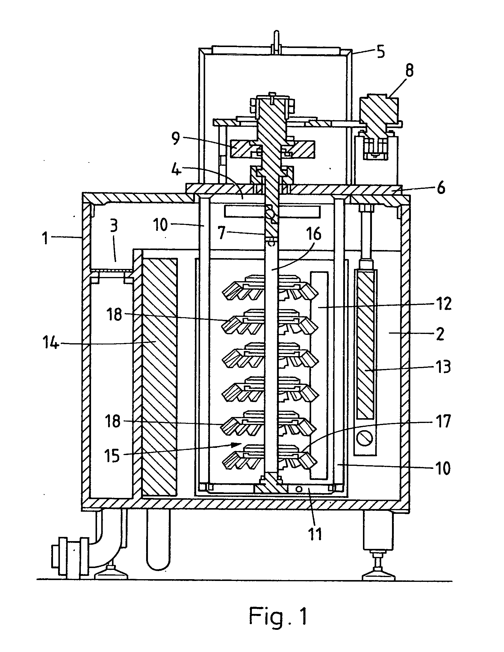
[0010]The coat-stripping unit according to the invention comprises a cuboid housing 1 which contains a tank 2 which consists of non-conductive material or is coated on the inside with a non-conductive material so that the inner surface is non-conductive. It serves for holding a liquid electrolyte. An overflow 3 with a screen or a filter is arranged next to the tank 2. At the top, the housing 1 has an opening 4.

[0011]A holder 5 comprises a baseplate 6 by means of which it is supported on the housing 1 and a coupling 7 which is rotatably mounted in the baseplate 6. Its axis of rotation runs vertically and approximately centrally through the tank 2. A drive device 8 which is in the form of an electric motor has an operative connection to the coupling 7. The holder 5 likewise comprises a two-pole current supply device (not shown), one pole of which has an electrically conductive connection via a current transmission device 9 to the coupling 7. It may be in the form of a current source, ...


PUM

PropertyMeasurementUnit
distanceaaaaaaaaaa
distanceaaaaaaaaaa
distanceaaaaaaaaaa

Abstract

A coupling (7) which is rotatable about a vertical axis of rotation and intended for the mounting of a workpiece support (15) which can be loaded, for example, with incorrectly coated or worn workpieces (18) is arranged in a removable holder (5) above a tank (2) filled with an electrolyte. Said workpiece support is connected via the coupling (7) to a current supply device, to the opposite pole of which an opposite electrode (12) is connected. A heating and cooling device (13) and an ultrasound generator (14) are also arranged in the tank (2). By current supply and simultaneous rotation, the coat is stripped from the workpiece support (15) and/or from the workpieces (18). After incorrect coating, the workpieces (18) together with the workpiece support (15) and in certain circumstances with the holder (5) can be taken over directly from a coating unit and, after coat stripping, transferred to such a coating unit for recoating.

Description

FIELD OF THE INVENTION[0001]The invention relates to a coat-stripping unit and a method for its operation. Coat-stripping units are used for freeing workpiece supports which are used in coating units and are inevitably also coated there from their coating and for making them suitable for use again and also for stripping the coat from worn or incorrectly coated workpieces and thus preparing them for recoating.THE PRIOR ART[0002]Mechanical methods, especially sand blasting, are predominantly used today for stripping the coat from workpiece supports. The workpiece supports have to be dismantled for this purpose. After the treatment, the sand has to be carefully removed, for example by blowing away. Nevertheless, frequently residues cannot be avoided, which may subsequently lead to malfunctions. Moreover, the workpiece supports are unevenly worn during the sand blasting and are subject to considerable wear, which shortens their life.[0003]For stripping the coat from worn and incorrectly...

Claims


Application Information

Patent Timeline
Patent Type & Authority Applications(United States)
IPC IPC(8): B23H9/00C25B9/00
CPCC23C14/021C25F7/00C23C14/5873C25F3/16C25F5/00
Inventor BAERTSCH, HANSPETEREGGER, SVENWURZER, MANFREDREYHER, TORSTENLASCH, KERSTINRAUCH, UDO
Owner OERLIKON SURFACE SOLUTIONS AG PFAFFIKON
Why Eureka
Try Eureka