System, Methods, Apparatuses and Computer Program Products for Use on a Machine Tool Controller

a controller and machine tool technology, applied in the field of device control technology, can solve the problems of large overhead, inability to provide integration of new machines, and difficulty in integrating new machines, so as to improve the capability of machine tools and enhance the operation of machine tools, the effect of low overhead and delay

Inactive Publication Date: 2008-03-06
OKUMA AMERICA CORP
View PDF8 Cites 26 Cited by
  • Summary
  • Abstract
  • Description
  • Claims
  • Application Information

AI Technical Summary

Benefits of technology

[0006] Accordingly, in order to address the problems described above, embodiments of the present invention provide methods, apparatuses and computer program products for providing a controller, such as a machine tool controller, capable of “plug 'n play” operation with partner devices and associated applications. In this regard, the machine tool controller of embodiments of the present invention is capable of recognizing newly installed partner devices and establishing communications with the partner devices automatically. Accordingly, for example, communication between a machine tool employing the machine tool controller and the partner devices may be accomplished with relatively low overhead and delay. Additionally, the capabilities of the machine tool may be continuously upgraded via installation of applications for enhancing machine tool operation. Such applications could be developed by any source including, for example, external vendors or even users themselves. Thus, embodiments of the present invention provide an open architecture by which software and devices may be added to machine tool systems regardless of the origin of the software and devices to be added.

Problems solved by technology

Since each of the machines may be manufactured by a different machine building company, although each machine may be capable of local control via a computer, the connections between each machine could be very complex.
For example, numerous expensive and customized cables and / or custom converters may be required to establish an interface between each of the machines in order to enable them to operate seamlessly.
As a result, when a new machine is added to a production chain, significant overhead may be involved in providing integration of the new machine.
Additionally, business practices of many machine vendors have developed proprietary practices that limit a manufacturer's ability to upgrade machines or utilize software or hardware from other machine builders.

Method used


Image

  • System, Methods, Apparatuses and Computer Program Products for Use on a Machine Tool Controller
  • System, Methods, Apparatuses and Computer Program Products for Use on a Machine Tool Controller
  • System, Methods, Apparatuses and Computer Program Products for Use on a Machine Tool Controller

Examples


Embodiment Construction

[0021] Embodiments of the present invention now will be described more fully hereinafter with reference to the accompanying drawings, in which some, but not all embodiments of the invention are shown. Indeed, the invention may be embodied in many different forms and should not be construed as limited to the embodiments set forth herein; rather, these embodiments are provided so that this disclosure will satisfy applicable legal requirements. Like reference numerals refer to like elements throughout.

[0022] As background, it should be understood that embodiments of the present application are designed to be implemented to enable the integration of multiple partner devices into a communication network especially for use in the machine tool industry where many peripheral partner devices work most efficiently when communicating directly with a machine tool.

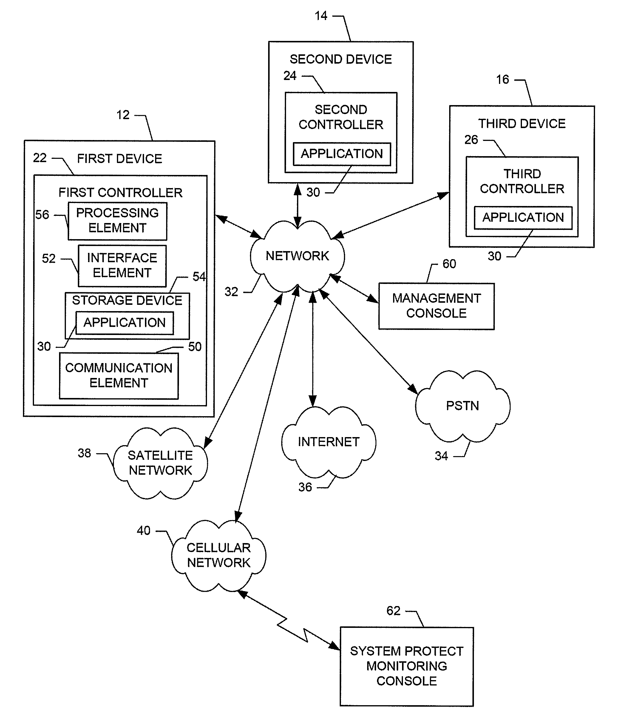
[0023]FIG. 1 is a diagram illustrating a system 10 for providing a controller, such as a machine tool controller, capable of “plug ...


PUM


Abstract

A method for providing a machine tool controller capable of “plug 'n play” operation with partner devices includes providing an application programming interface (API) capable of executing software associated with at least one partner device, providing a machine tool controller configured to run the API, and enabling communication between the machine tool controller and the at least one partner device over a network enabled by the API.

Description

CROSS REFERENCE TO RELATED APPLICATION [0001] This application claims the benefit of U.S. Provisional Application No. 60 / 824,508, filed Sep. 5, 2006, the contents of which are incorporated herein in their entirety.FIELD OF THE INVENTION [0002] Embodiments of the present invention relate generally to device control technology, and more particularly, to providing a controller capable of “plug 'n play” operation with partner devices and associated applications for machine tools. BACKGROUND OF THE INVENTION [0003] Many organizations have taken a strong interest in increasing organizational productivity. Such increases are achieved in numerous ways including streamlining procedures, improving equipment, improving worker training, improving safety, reducing waste, reducing downtime, etc. As an example, in the manufacturing industry, many organizations have increasingly turned to automation of production. As technology continues to advance, manufacturing equipment has become increasingly p...

Claims


Application Information

Patent Timeline
Patent Type & Authority Applications(United States)
IPC IPC(8): G05B15/00
CPCG05B19/41845G05B2219/31457G05B2219/31107G05B2219/31104
Inventor TAIN, ROBERTSIDES, BRIANNEWMAN, BRYAN
Owner OKUMA AMERICA CORP
Why Eureka
Try Eureka