Low cost, high performance error detection and correction

a high-performance, error-detecting technology, applied in the direction of instruments, coding, code conversion, etc., can solve the problems of high cost, inability to provide adequate resilience, and inability to meet the requirements of space-constrained design and replication of large components, such as memories, to achieve low cost, reduce overhead, and reduce circuit complexity and cost

Inactive Publication Date: 2008-03-06
RGT UNIV OF CALIFORNIA
View PDF4 Cites 28 Cited by
  • Summary
  • Abstract
  • Description
  • Claims
  • Application Information

AI Technical Summary

Benefits of technology

[0014]The present invention discloses a method for concurrent error detection and correction (EDC). Specifically, the present invention discloses a designer-driven, automated method for synthesizing EDC in a digital circuit through use of a subset of low density linear parity check (LDPC) codes, wherein the codes provide a circuit-based solution for local error recovery at low cost. Circuit-efficient encodings are generated that inherently provide tolerance to constant error rates in excess of one error per cycle. Moreover, these codes allow for lower circuit complexity and cost than existing techniques such as Hamming, Partitioned Hamming and triple modular redundancy (TMR). While existing techniques aim to reduce the overhead in terms of the number of check bits, this technique aims specifically to reduce circuit area, delay, and power.

Problems solved by technology

While SEU compliant machines should be able to operate under constant error rates of one fault per cycle, many do not, due to prohibitive overhead, and thus many machines are often only partially SEU tolerant.
In general, existing error detection and correcting (EDC or EDAC) solutions suffer from high cost and fail to provide adequate levels of resilience.
While TMR is well suited for latency-sensitive applications [7], such as high-performance processors, its extreme area overhead makes it impractical for space-constrained designs and replication of large components, such as memories.
By contrast, Hamming codes provide optimal density in terms of added storage (flip-flop / memory) overhead, but incur significant latency penalties due to deep parity trees and decoding logic.
While effective, neither technique provides a middle ground solution capable of meeting design constraints in many applications.
Though the SEU model is effective for terrestrial radiation fault mechanisms, electrical (EMI [electromagnetic interference]) and space-borne radiation effects may generate multiple faults, especially in nanometer scaled memory systems.
Furthermore, the tendency for combinatorial logic errors to be automatically screened via logic and timing mechanisms increases the applicability of EDAC memory techniques over plenary SEU fault tolerant techniques like TMR [3].
Though the low latency of TMR implementations makes it an appealing choice for high speed logic, 3× replication is impractical in many cases.
The fault correction capabilities of TMR are additionally limited by an inability to correct multi-bit errors when they occur in multiple copies (voting requires two out of three copies to be correct).
Three-way voting is highly ineffective on pattern-dependent error phenomenon commonly experienced in memories.
While one might think voting logic can be optimized to address these scenarios, it becomes increasingly difficult to route wires given latency and area constraints.
EDAC, on the other hand, has seen limited use in high performance digital logic due to the deep parity trees and dense decoding circuits that typically arise from Hamming-based implementations.
The logic tree for each parity bit has depth lg2 (n)−1, resulting in latencies that are difficult to mitigate in high performance designs.
A more insidious delay is related to the full binary decoding circuits required for correction and the loading on parity trees to drive the decoding logic.
Furthermore, design area is impacted by the number of parity trees necessary for single error correction (SEC).
As block size increases, both latency and area increase due to added fan in delay and routing congestion of syndrome decoding networks.

Method used


Image

  • Low cost, high performance error detection and correction
  • Low cost, high performance error detection and correction
  • Low cost, high performance error detection and correction

Examples


Embodiment Construction

[0022]In the following description, reference is made to the accompanying drawings which form a part hereof, and which is shown, by way of illustration, several embodiments of the present invention. It is understood that other embodiments may be utilized and structural changes may be made without departing from the scope of the present invention.

Overview

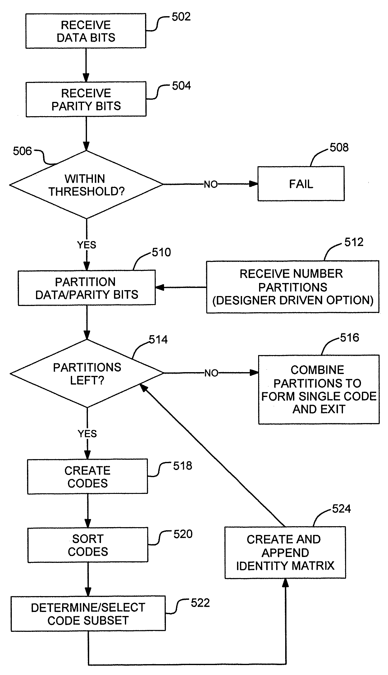
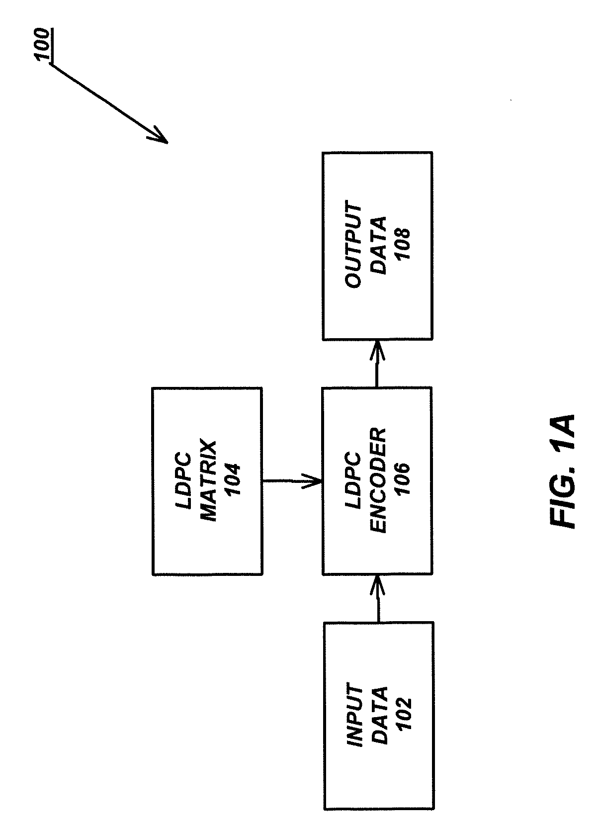
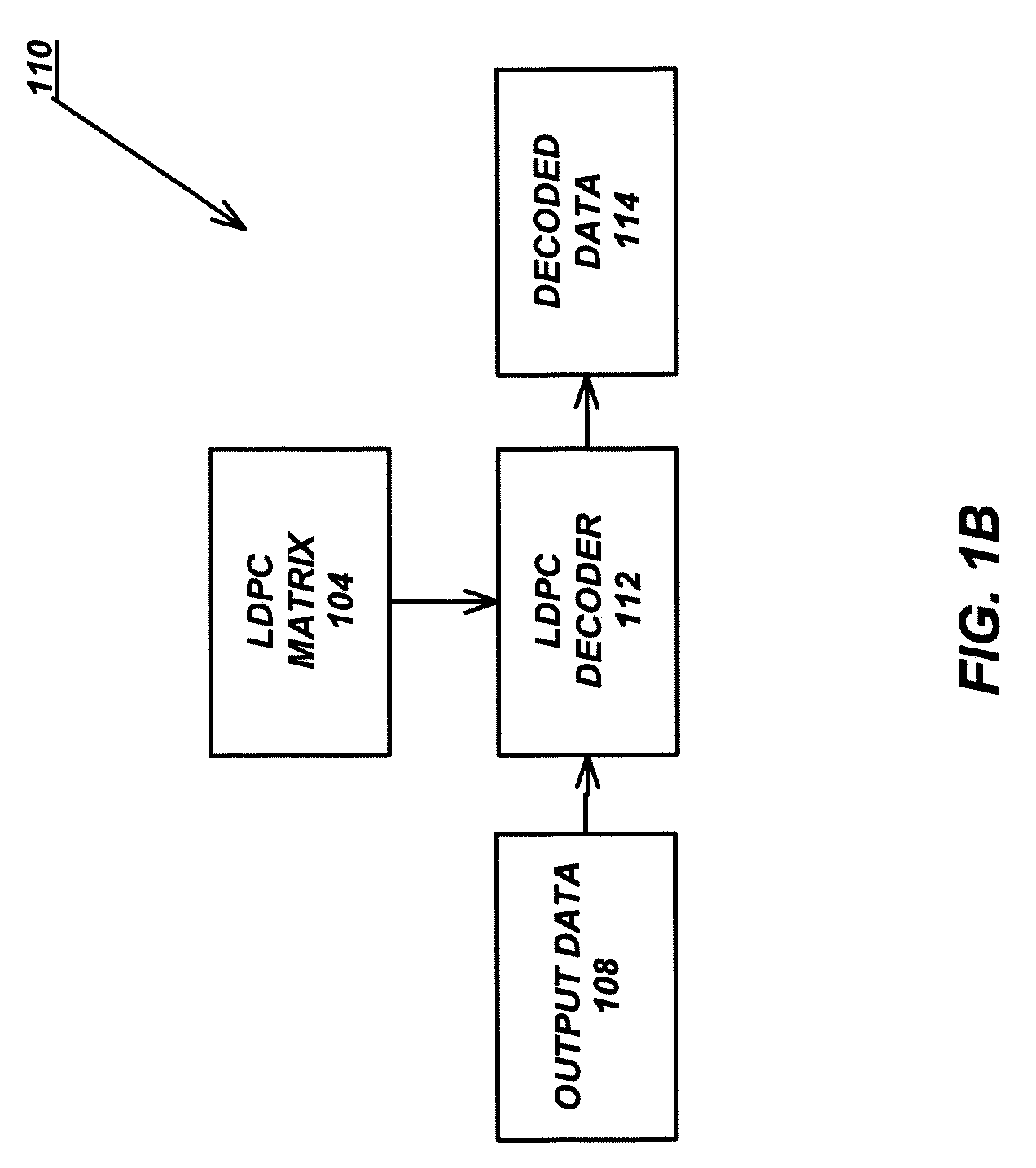
[0023]The present invention comprises a family of linear parity check codes that lend themselves to optimal EDC circuits in terms of circuit area, delay, and power. Embodiments provide a technique for constraint-driven construction of optimal and near-optimal codes capable of multi-bit error correction. Additionally, the custom-built codes may be automatically applied to digital circuits including finite-state-machines (FSM) and memories.

[0024]The novel EDC technique allows for the construction of machines that are resilient to single bit errors with relatively little overhead in terms of both added redundancy and logic complexity. T...


PUM


Abstract

A method and apparatus provides the ability to build and use low-density linear parity-check (LDPC) codes for implementing error detection and correction (EDC). A number of data bits and a number of parity bits are received. While the number of data bits and number of parity bits are within a defined threshold with respect to each other, codes are created. The codes are based on the number of parity bits as combinations of values for the parity bits. The codes are sorted into weight subsections with each subsection containing having the same weight. A subset of each subsection is determined based on the number of data bits with the subset containing codes representing a lowest number of inputs to a parity tree for a given parity bit. An identity matrix of a size of the number of data bits is appended to the subset.

Description

CROSS-REFERENCE TO RELATED APPLICATIONS[0001]This application claims the benefit under 35 U.S.C. Section 119(e) of the following co-pending and commonly-assigned U.S. provisional patent application(s), which is / are incorporated by reference herein:[0002]Provisional Application Ser. No. 60 / 824,420, filed Sep. 1, 2006, by Forrest D. Brewer and Gregory W. Hoover, entitled “CONCURRENT ERROR DETECTION AND CORRECTION,” attorneys' docket number 3074.194-US-P1.BACKGROUND OF THE INVENTION[0003]1. Field of the Invention[0004]The invention is related to a method for concurrent error detection and correction.[0005]2. Description of the Related Art[0006](Note: This application references a number of different publications as indicated throughout the specification by reference numbers enclosed in brackets, e.g., [x]. A list of these different publications ordered according to these reference numbers can be found below in the section entitled “References.” Each of these publications is incorporate...

Claims


Application Information

Patent Timeline
Patent Type & Authority Applications(United States)
IPC IPC(8): G06F11/00
CPCH03M13/033H03M13/1102H04L1/0057H04L1/005H04L1/0041
Inventor BREWER, FORREST D.HOOVER, GREGORY W.
Owner RGT UNIV OF CALIFORNIA
Why Eureka
Try Eureka