
Pneumatic Radial Tire For Light Truck

Inactive Publication Date: 2008-03-13
YOKOHAMA RUBBER CO LTD
View PDF4 Cites 4 Cited by
  • Summary
  • Abstract
  • Description
  • Claims
  • Application Information

AI Technical Summary

Benefits of technology

[0006] An object of the present invention is to provide a pneumatic radial tire for a light truck which is designed to improve the contact shape, to suppress the growth and strain of a belt edge portion due to the creep strain of a carcass layer, and to prevent the separation failure at the belt edge portion.
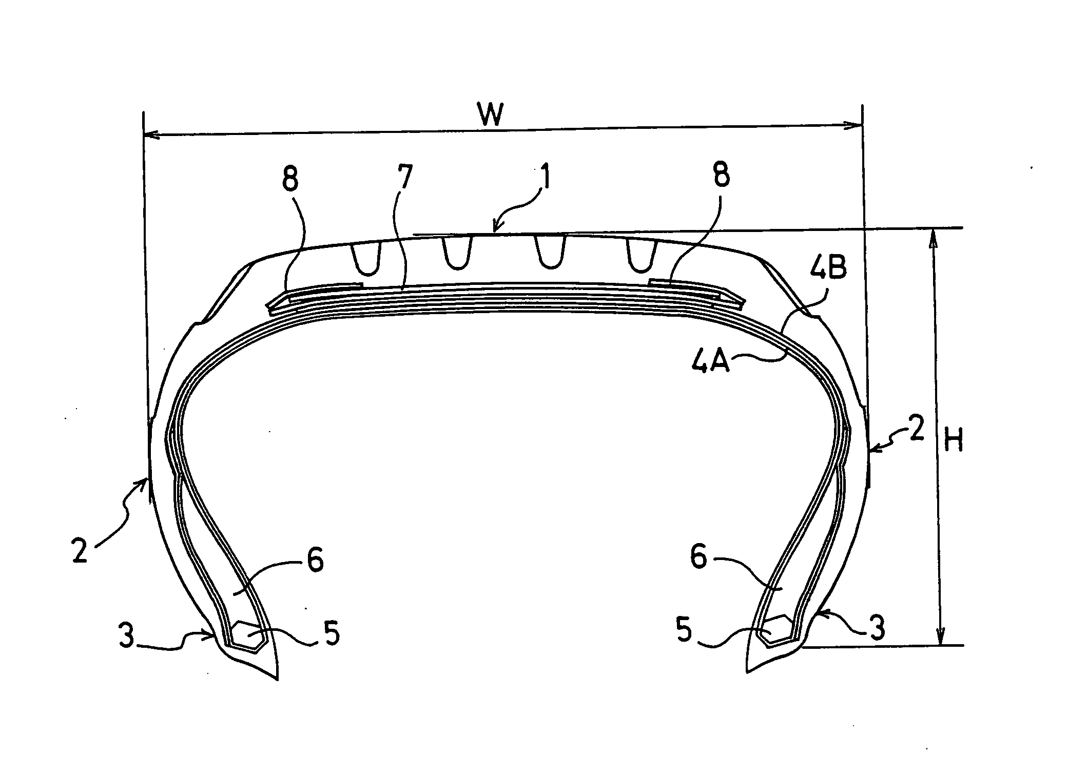
[0008] In the present invention, in the pneumatic radial tire for a light truck, which includes the carcass layer formed of the organic fiber cords, and for which the air pressure used is relatively high, the belt cover layer is disposed around the edge portion of the belt layer, the belt cover layer comprising the organic fiber cord wound around the tire in a circumferential direction of the tire, the organic fiber cord having a low intermediate elongation. Accordingly, it is made possible to prevent the contact length in the shoulder area from being elongated under a high-load use condition, and to improve the contact shape from the time when the tire is brand-new to the final stage of the wear life. As a result, it is possible to prevent the occurrence of the shoulder wear. In addition, since the belt cover layer is added, it is possible to suppress the growth and strain of the belt edge portion due to the creep strain of the carcass layer, and to prevent the separation failure at the belt edge portion. Thus, it is possible to increase the durability lasting until the final stage of the wear life.
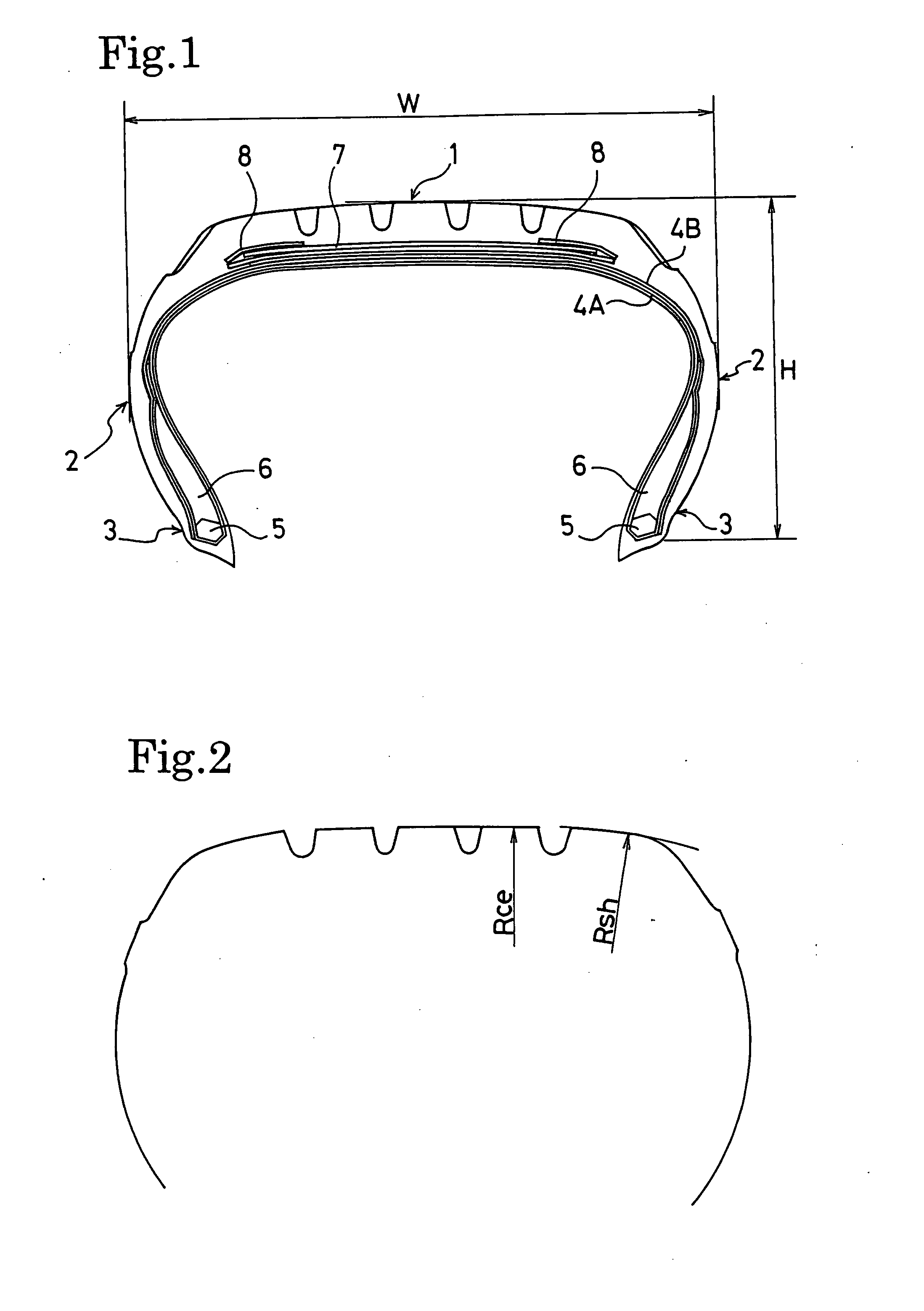
[0009] It is preferable that the pneumatic radial tire for a light truck have a tread profile such that, in relation to a curvature radius Rce in a center area of a tread portion, a curvature radius Rsh in a shoulder area of the tread portion satisfies Rsh<Rce, and more preferably satisfies Rsh<0.5Rce, when the tire is mounted on a standard rim and the air whose pressure corresponds to the maximum load carrying capacity is filled into the tire. When the curvature radius Rsh in the shoulder area is set relatively small, and the difference between the diameters in the center and shoulder areas is set large, it is possible to prevent the contact length in the shoulder area from being elongated. Accordingly, it is possible to optimize the contact shape under a high-load use condition by virtue of the synergy effect between the tread profile and the belt cover layer.
[0010] It is preferable that, in addition to that the organic fiber cord forming the belt cover layer has such an intermediate elongation, the organic fiber cord have a structure in which a plurality of fiber bundles are stranded, at least one of the fiber bundles being made of one of polyethylene-2,6-naphthalate and polyethylene terephthalate. Such an organic fiber cord exhibits a favorable hooping effect.

Problems solved by technology

For this reason, there is a problem that the shoulder wear tends to occur since the contact length in the shoulder area becomes longer than that in the center area.
However, under present circumstances, especially for the tires with an aspect ratio of 70% or less, a sufficient effect of improving the contact shape cannot be obtained only by setting the curvature radius in the shoulder area small, and providing the relative difference of the diameters in the tread portion.
However, for the pneumatic radial tire for a light truck, since the air pressure used is high, and it is used under a high load condition, there is a case where the creep strain occurs in the carcass layer as the mileage increases, and the carcass periphery is elongated.
There is a problem that, when the creep strain occurs in the carcass layer, the strain occurring in the belt edge portion increases, and the separation failure at the belt edge portions tends to occur toward the final stage of the wear life.
However, for the pneumatic radial tire for a light truck, since the air pressure used is high, and the tire is used under a high load condition, there is a possibility that the creep strain occurs in the belt cover layer as in the case of the carcass layer.

Method used


Image

  • Pneumatic Radial Tire For Light Truck
  • Pneumatic Radial Tire For Light Truck

Examples


examples

[0027] The tires of examples 1 to 3 and a conventional example were respectively fabricated as follows. In the pneumatic radial tire for a light truck, in which the tire size was 205 / 60R17.5; the carcass layer was formed of organic fiber cords; the tire had a casing structure in which the three belt layers were disposed on the radially outer side of the carcass layers; and the air pressure corresponding to the maximum load carrying capacity was 600 kPa, belt cover layers were added around both edge portions of the belt layers, and the intermediate elongation of the organic fiber cord forming the belt cover layer under a load of 67 N was varied. In addition, in the tires of the examples 1 to 3 and the conventional example, the curvature radius Rsh in the shoulder area of the tread portion and the curvature radius Rce in the center area of the tread portion, which were given when the tire is mounted on a standard rim and the air whose pressure corresponds to the maximum load carrying ...


PUM


Abstract

Provided is a pneumatic radial tire for a light truck which is designed to improve the contact shape, to suppress the growth and strain of a belt edge portion due to the creep strain of a carcass layer, and to prevent the separation failure at the belt edge portion. The pneumatic radial tire of the present invention is one, in which a carcass layer is formed of organic fiber cords, the tire has a casing structure in which at least two belt layers are disposed on a radially outer side of the carcass layer, and an air pressure corresponding to the maximum load carrying capacity is in the range of 350 to 650 kPa, wherein a belt cover layer is disposed around an edge portion of the belt layer, the belt cover layer comprising an organic fiber cord wound around the tire in a circumferential direction of the tire, the organic fiber cord having an intermediate elongation of at most 5.5% under a load of 67 N.

Description

FIELD OF THE INVENTION [0001] The present invention relates to a pneumatic radial tire suitable for a light truck, and more specifically to a pneumatic radial tire for a light truck, which is designed to improve the contact shape, to suppress the growth and strain of a belt edge portion due to the creep strain of a carcass layer, and to prevent the separation failure at the belt edge portion. DESCRIPTION OF THE RELATED ART [0002] In general, with regard to the pneumatic radial tire for a light truck, since the tire is used under a high load condition, there is a tendency that the contact pressure in the shoulder area of the tread portion becomes relatively high compared to that in the center area of the tread portion. For this reason, there is a problem that the shoulder wear tends to occur since the contact length in the shoulder area becomes longer than that in the center area. [0003] As a measure against this problem, the method generally adopted is to prevent the contact length ...

Claims


Application Information

Patent Timeline
IPC IPC(8): B60C9/02B60C1/00
CPCB60C9/2204Y10T152/10855B60C11/0083B60C2009/2209
Inventor OSAKI, MICHIO
Owner YOKOHAMA RUBBER CO LTD
Learn More