Mount with magnetic attachment and automatic safety latching

a technology of mounting device and magnetic attachment, which is applied in the direction of lightening support device, washstand, scaffold accessories, etc., can solve the problems of projector damage, assembly and installation, and unfortunately, a number of new problems

Active Publication Date: 2008-03-13
GAMBER JOHNSON
View PDF30 Cites 61 Cited by
  • Summary
  • Abstract
  • Description
  • Claims
  • Application Information

AI Technical Summary

Benefits of technology

[0020]In another embodiment, the pivot arm includes an aperture therethrough and further including a locking fastener sized to be received withi

Problems solved by technology

This placement had inherent drawbacks in that passers-by may block the projected image or inadvertently bump the table and knock the projector out of alignment, or even worse, liquid spillages on the conference table may damage the projector.
In the wake of solving some of the aforementioned problems, this mounting method unfortunately created a number of new problems.
Foremost is the problem of assembly and installation.
Because each installation may be different, the installers ha

Method used


Image

  • Mount with magnetic attachment and automatic safety latching
  • Mount with magnetic attachment and automatic safety latching
  • Mount with magnetic attachment and automatic safety latching

Examples


Embodiment Construction

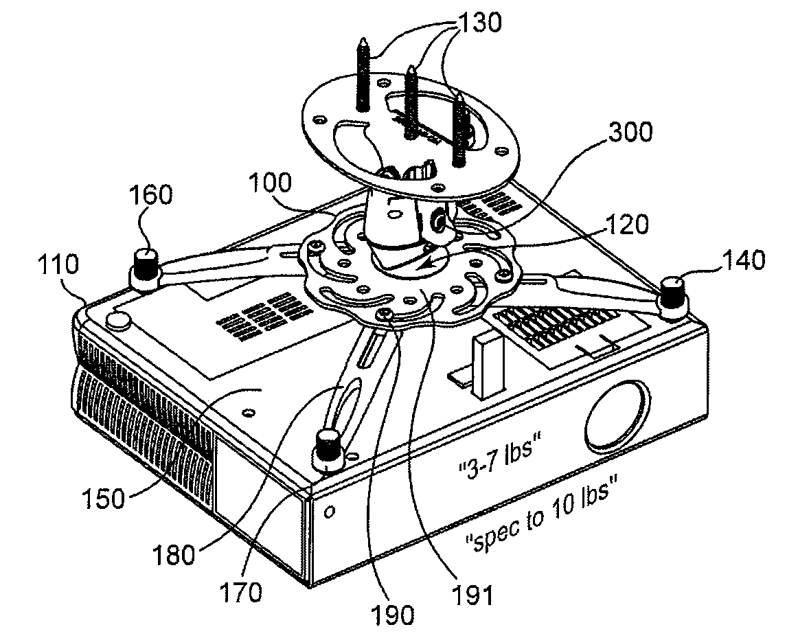
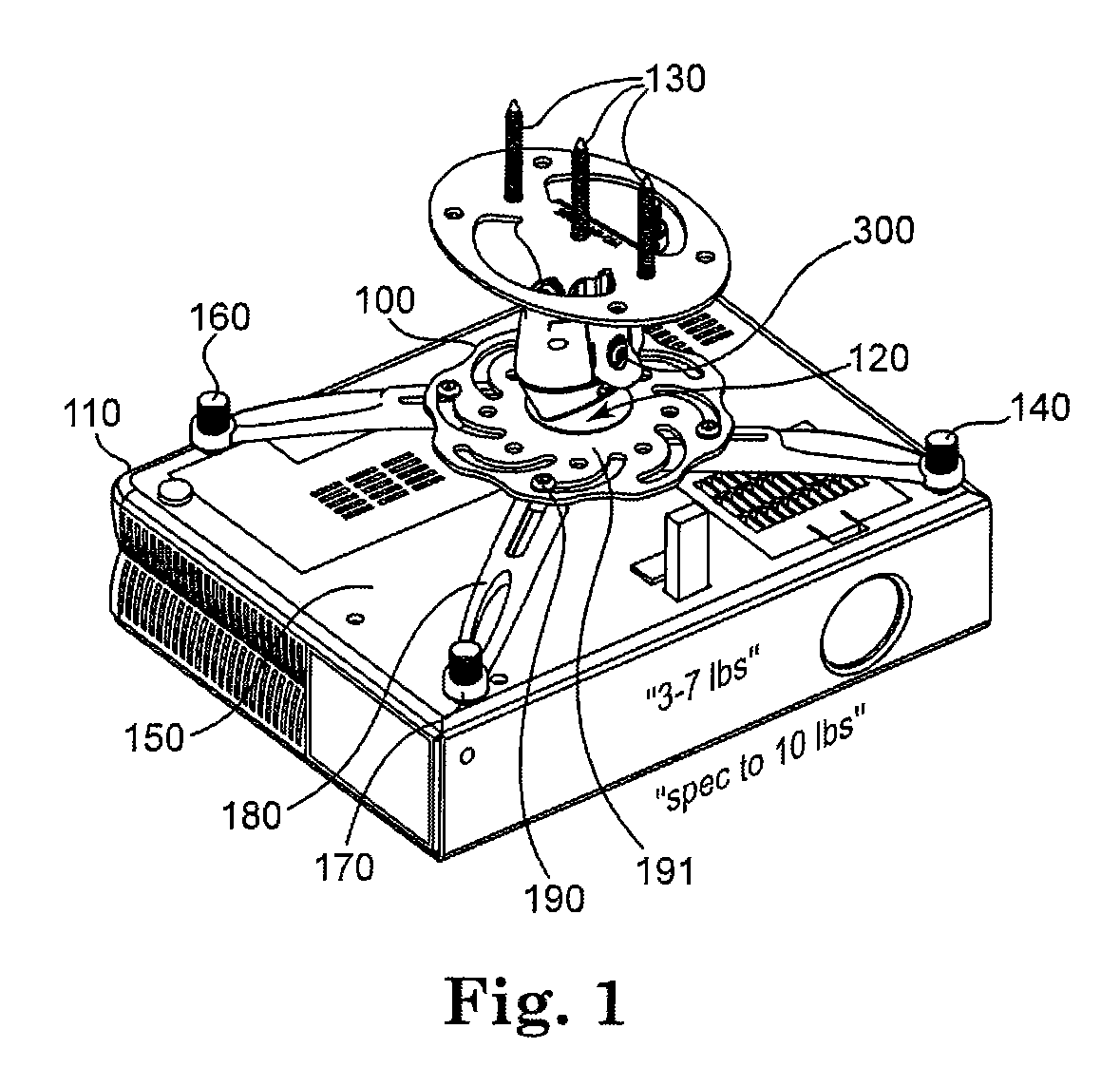
[0036]In general, the present invention is directed to supporting structures for video projectors and more particularly to an apparatus for mounting such a device to a ceiling. The preferred embodiments of the invention provide a convenient method for both attaching and disengaging a video projector to and from its ceiling attached mount without the use of cumbersome tools such as screwdrivers, wrenches, and the like which can be awkward when used overhead. The invention also describes a convenient method for adjusting the projected video image to a desired screen location after the projector has been securely mounted to the ceiling, wherein the installer does not have to support the weight of the projector overhead while simultaneously attempting to mount and align the projector.

[0037]FIG. 1 shows one embodiment of a mounting device 100 mechanically attached to a video projector 110 on its bottom surface via screw 120 (not shown in FIG. 1), and which may in turn be secured to an ov...


PUM


Abstract

A system and method of releasably mounting a device, usually to a ceiling, is disclosed. The system has a ceiling mounted unit (200) and a device mounted unit (250), releasably joined preferably by an magnetic coupling (202) which engages a floating plate (252) allowing for positive coupling even if the units are misaligned. A safety latch (256) with a locking/latching claw (260) and ejection/disengagement prong (266) provide positive locking and a method of separating the units despite strong adhesion forces.

Description

CROSS-REFERENCE TO RELATED APPLICATION[0001]The present application claims the benefit of U.S. Provisional Application Ser. No. 60 / 844,138 filed on 13 Sep. 2006, the complete subject matter of which is hereby incorporated herein by reference in its entirety.FIELD OF THE INVENTION[0002]The present invention is directed generally to supporting structures for mounting devices, such as video projectors to a ceiling or other surface.BACKGROUND[0003]Video projectors and other ceiling mounted devices have been available for many years and are an integral part of both business and educational presentations. Early versions of these projectors were typically rested on a conference table or any convenient available surface and manually aimed at the intended viewing surface or screen. This placement had inherent drawbacks in that passers-by may block the projected image or inadvertently bump the table and knock the projector out of alignment, or even worse, liquid spillages on the conference ta...

Claims


Application Information

Patent Timeline
IPC IPC(8): F21V21/03F21V17/10F21V21/096
CPCF16M11/04F16M11/041F16M11/043F21V21/096F16M11/14F16M13/02F21V21/03F16M11/12
Inventor BOUISSIERE, MICHAEL F.
Owner GAMBER JOHNSON
Why Eureka
Try Eureka