Microstructured Infrared Sensor

Inactive Publication Date: 2008-03-13
ROBERT BOSCH GMBH
View PDF4 Cites 29 Cited by
  • Summary
  • Abstract
  • Description
  • Claims
  • Application Information

AI Technical Summary

Benefits of technology

[0006] The infrared sensor according to the present invention and the method for manufacturing same have the advantage over the related art that a co

Problems solved by technology

However, in the tolerance-based situation in which the sensor is installed on the housing base, the window is not able to be accurately matched to the lateral dimension of the absorber layer.
Since the sensitivity of the infrared sensor is defined by the temperature difference between the warm contact area under the absorber layer and the cold ends of the printed conductors provided in the bulk mate

Method used


Image

  • Microstructured Infrared Sensor
  • Microstructured Infrared Sensor
  • Microstructured Infrared Sensor

Examples


Embodiment Construction

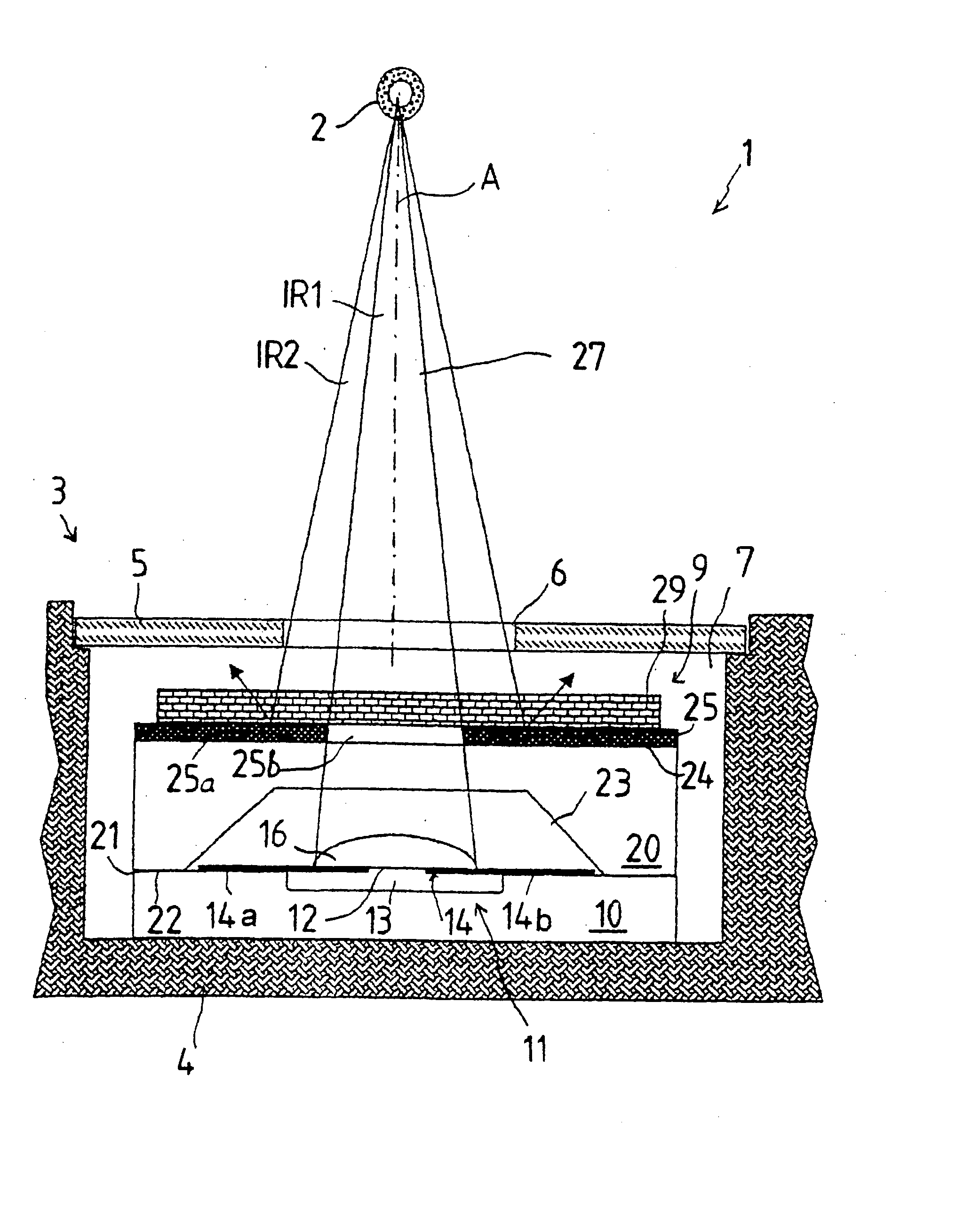
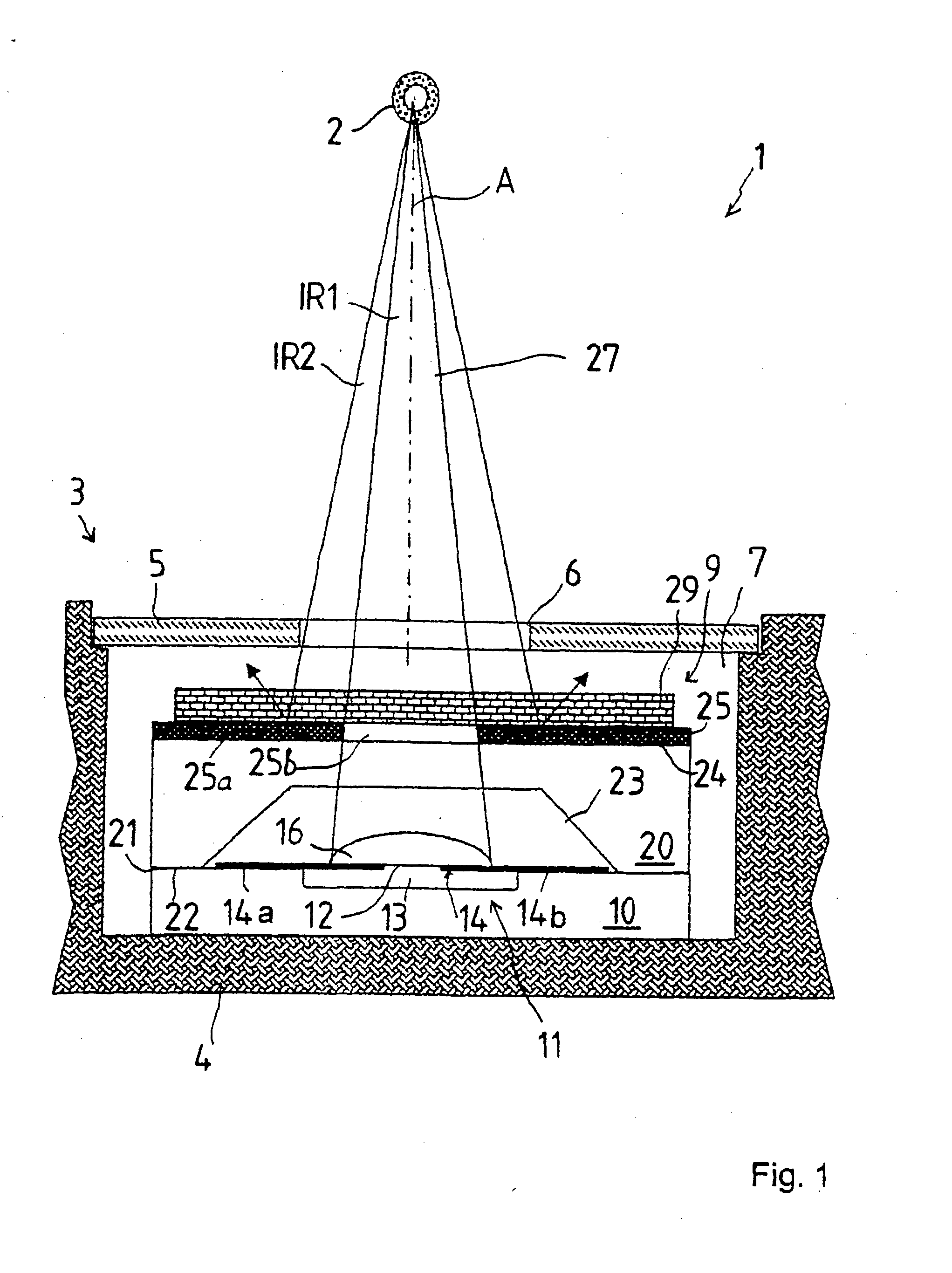
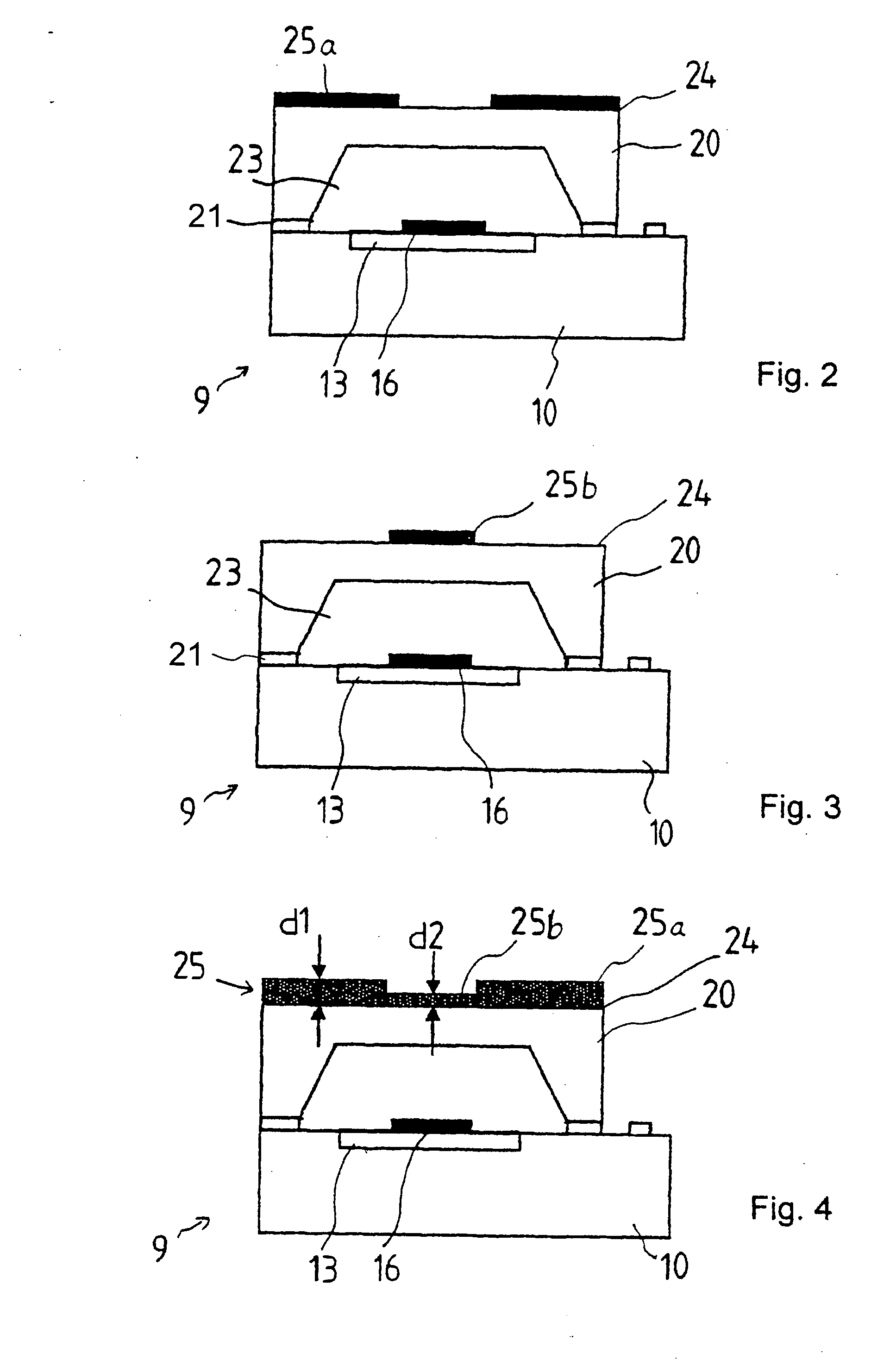
[0020] An infrared (IR) sensor system 1 shown in FIG. 1 has an IR radiation source 2, for example, a low-current incandescent lamp, and a sensor module 3 having a housing 4 made of plastic or a molding compound, for example, and a cover 5 attached to housing 4 having a window 6. Provided in internal housing space 7 formed between housing 4 and cover 5 is an infrared sensor 9, for example, glued onto the base of housing 4. Infrared sensor 9 has a sensor chip 10 having a measuring structure 11 which detects IR radiation, measuring structure 11 having a diaphragm 12 formed on the top side of sensor chip 10, a cavity 13 formed underneath diaphragm 12, and at least one thermopile structure 14 formed on diaphragm 12 and having two printed conductors 14a, 14b. Printed conductors 14a and 14b are made of different electrically conductive materials, for example, polycrystalline silicon and a metal, for example, aluminum. They are contacted in a central region of diaphragm 12 and run laterally...


PUM


Abstract

An infrared sensor having at least one measuring structure, which has, for example, a sensor chip having a measuring structure and a cap chip which is attached to the sensor chip and, together with the sensor chip, defines a sensor space; a screen having an internal screen area and an external screen area surrounding the internal screen area being formed on the top side of the cap chip; the internal screen area which is transparent to the infrared radiation to be detected being formed above the measuring structure, and the external screen area being at least partly non-transparent for the incident infrared radiation. The external screen area may be designed in particular as a reflective coating of metal or a dielectric layer, as reflective structuring formed by trenches having oblique surfaces, or as absorbing structuring.

Description

BACKGROUND INFORMATION [0001] Microstructured infrared sensors may be used in particular in gas detectors in which an IR radiation emitted by a radiation source, for example, an incandescent bulb operated in the low-current range or an IR LED, is transmitted over an absorption path and subsequently received by the infrared sensor, and the concentration of the gases to be detected in the absorption path is inferred from the absorption of the infrared radiation in specific wavelength ranges. Gas sensors of this type may be used in particular in the automotive industry, for example, for detecting a leak in an AC unit operated using CO2 or for checking the air quality of the ambient air. [0002] The micromechanical infrared sensor normally has a sensor chip having a measuring structure which is sensitive to infrared radiation and a cap chip covering the sensor chip. A sensor space, sealed to the outside in a vacuum-tight manner, is formed between the sensor chip and the cap chip, a cavit...

Claims


Application Information

Patent Timeline
IPC IPC(8): G01J5/02G01J5/10G01J5/20
CPCG01J5/0014G01J5/02G01J5/0225G01J5/024G01J5/045G01J5/06G01N2021/317G01J5/0803G01J5/0831G01J5/0875G01J5/12G01N21/3504G01N2021/3137G01J5/08
Inventor FRANZ, JOCHENREICHENBACH, FRANKMAURER, DIETERHOEFER, HOLGERSCHWEIKER, MARK-ALEXANDER
Owner ROBERT BOSCH GMBH
Why Eureka
Try Eureka