Carbon Nanotube (CNT) Extrusion Methods And CNT Wire And Composites

a carbon nanotube and extrusion method technology, applied in the manufacture of electric discharge tubes/lamps, electrode systems, applications, etc., can solve the problems of limited fiber strength and much too short tubes to perform spinning action, and achieve the effect of longer cnt lengths

Inactive Publication Date: 2008-03-13
CAPIZZO PETER DAVID
View PDF2 Cites 44 Cited by
  • Summary
  • Abstract
  • Description
  • Claims
  • Application Information

AI Technical Summary

Benefits of technology

[0010] The present disclosure is directed toward a novel use of the catalyst action of shape-shifting to achieve longer CNT lengths. The method significantly differs from present tube growth methods in that, to produce CNT wire, an extrusion process is utilized. Present tube growth forming methods result in tubes that are much too short to perform a spinning action to produce a CNT yarn or weaved cable of significant strength. Even with tubes long enough to spin, the fiber strength will be limited to the interconnecting bond between tubes. What is needed is a continuous extrusion method of making CNT continuous wire, so that the CNT strength is maintained through the entire length of the wire or cable. But the continuous part of the process needs only be the net result. That is, a discrete step-by-step oscillator can build on the forming end of a CNT without the physical limits of a catalyst, and the net result is an endless extrusion.

Problems solved by technology

Present tube growth forming methods result in tubes that are much too short to perform a spinning action to produce a CNT yarn or weaved cable of significant strength.
Even with tubes long enough to spin, the fiber strength will be limited to the interconnecting bond between tubes.

Method used


Image

  • Carbon Nanotube (CNT) Extrusion Methods And CNT Wire And Composites
  • Carbon Nanotube (CNT) Extrusion Methods And CNT Wire And Composites
  • Carbon Nanotube (CNT) Extrusion Methods And CNT Wire And Composites

Examples


Embodiment Construction

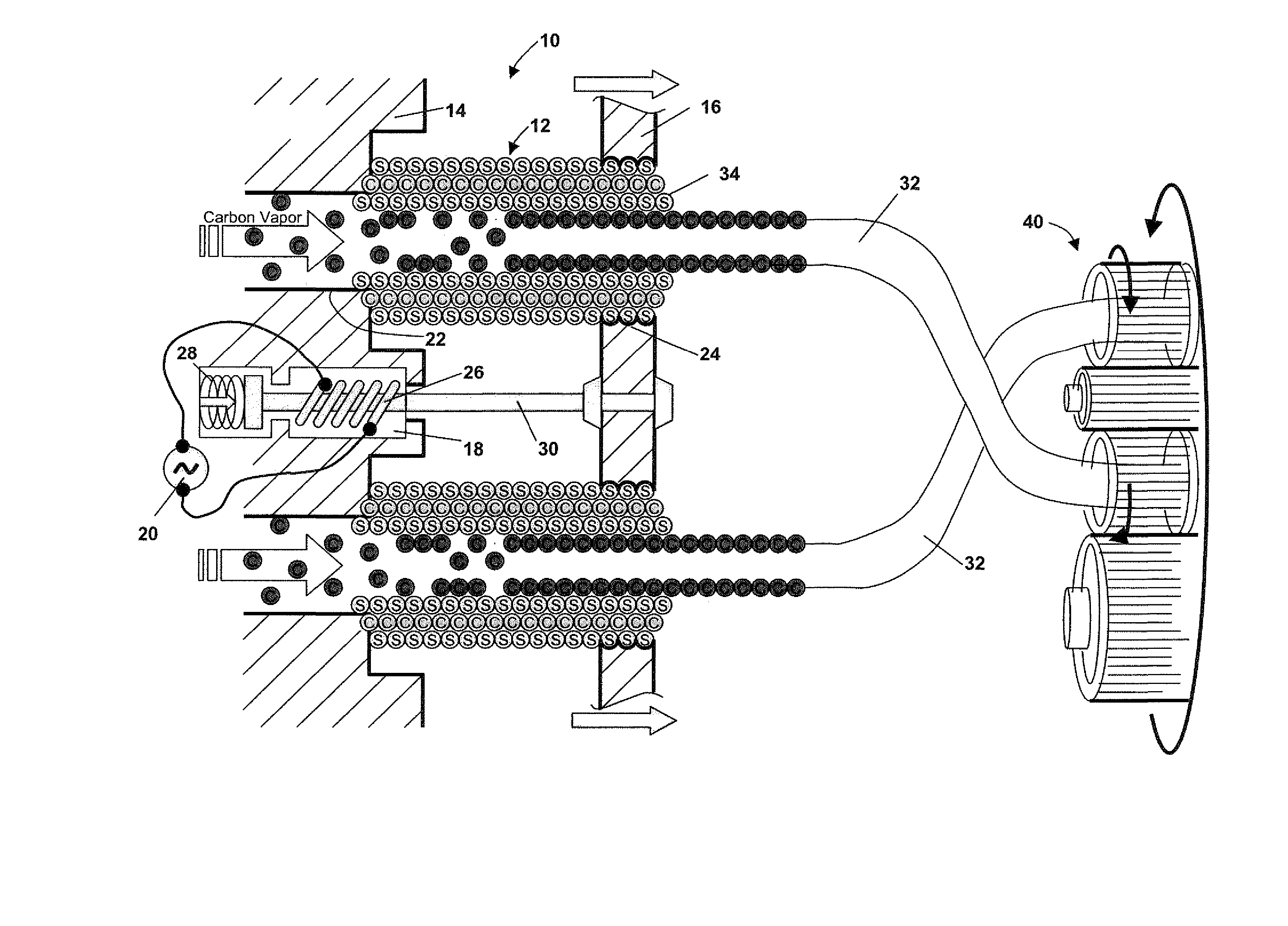
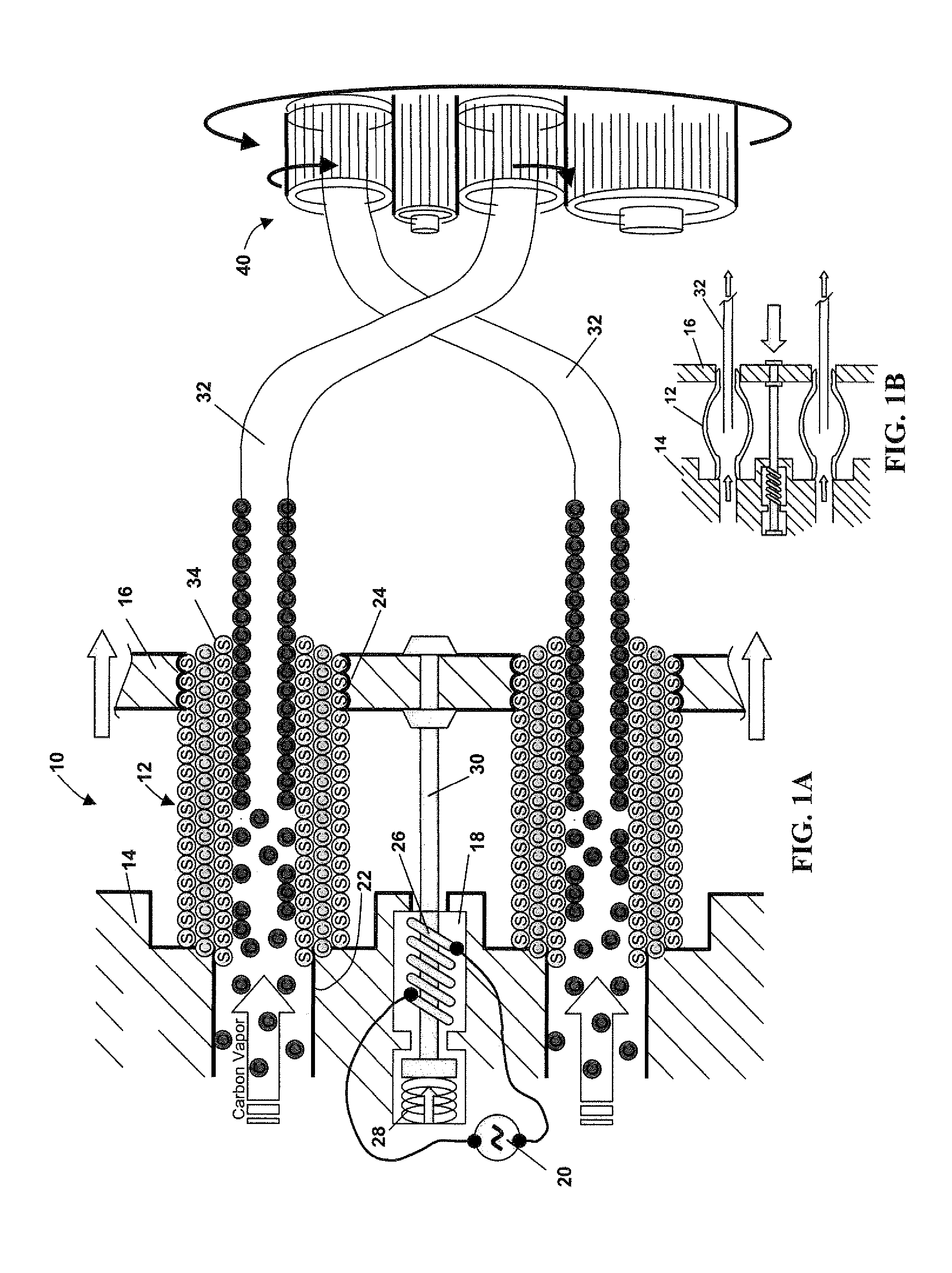
[0026] While the present invention is described with respect to a method and apparatus for extruding CNT to form CNT stranded or solid wire, the present invention may be adapted and utilized for creating long-strand CNT for other uses including CNT extrusions spun or woven into filaments, fibers, strands, strings, rope, cable, yarn, fabric or twine. These materials can comprise continuous extrusion CNT, or long-stranded CNT, or combinations of continuous and long-stranded CNT.

[0027] In the following detailed description, spatially orienting terms may be used such as “left,”“right,”“vertical,”“horizontal,” and the like. It is to be understood that these terms are used for convenience of description of the components or embodiments by reference to the drawings. These terms do not necessarily describe the absolute location in space, such as left, right, upward, downward, etc., that any part must assume.

[0028] In the following description, various operating parameters and components a...


PUM

PropertyMeasurementUnit
pressuresaaaaaaaaaa
diameteraaaaaaaaaa
diameteraaaaaaaaaa

Abstract

A carbon nanotube (CNT) extrusion system includes a carbon source, an extrusion die having a baseplate having a plurality of die sets, each die set has a plurality of through-holes in fluid communication with the carbon source and a corresponding plurality of template tubes connected at one end to the baseplate and coaxial with the through-holes, each template tube includes a catalyst for forming a CNT structure in combination with the carbon source. An oscillating mechanism operatively associated with the free end of each template tube axially oscillates the template tubes to alternately form and release the CNT structure within each template tube in a continuous manner. The oscillating mechanism can be an alternating electric field or magnetic field applied to the template tubes, the frequency of the electric or magnetic field being synchronized with a formation rate of the CNT within the template tubes.

Description

CROSS-REFERENCE TO RELATED APPLICATION [0001] The present application claims priority to U.S. provisional application Ser. No. 60 / 803,740 filed Jun. 2, 2006, titled “Carbon Nanotube (CNT) Extrusion Methods and CNT Wire and Composites”.TECHNICAL FIELD [0002] The present invention relates to carbon nanotube (CNT) wire and composites, and methods for making the same. BACKGROUND [0003] One of the greatest problems facing space programs has been, and continues to be, the cost of putting payloads into space. That cost is a direct consequence of the launch system weight required to get a given payload out of the earth's gravity well. With current technology, that equates to about $25,000 or more for every 1 pound of payload just to get to orbit. Lunar or Mars missions will cost much more. [0004] In an effort to reduce this cost ratio, space agencies have implemented payload-to-orbit cost reduction initiatives. These initiatives have included several new technologies and demonstrator progra...

Claims


Application Information

Patent Timeline
Patent Type & Authority Applications(United States)
IPC IPC(8): B29C35/08
CPCH01J9/025D01F9/00B29C47/0004D01F9/127B29C48/022
Inventor CAPIZZO, PETER DAVID
Owner CAPIZZO PETER DAVID
Why Eureka
Try Eureka