
Detection of the instantaneous position of a linearly reciprocating member using high frequency injection

a technology of instantaneous position and linear reciprocating, which is applied in the direction of piston pumps, pump parameters, instruments, etc., can solve the problems of adding weight and additional expens

Inactive Publication Date: 2008-03-13
SUNPOWER
View PDF5 Cites 7 Cited by
  • Summary
  • Abstract
  • Description
  • Claims
  • Application Information

AI Technical Summary

Benefits of technology

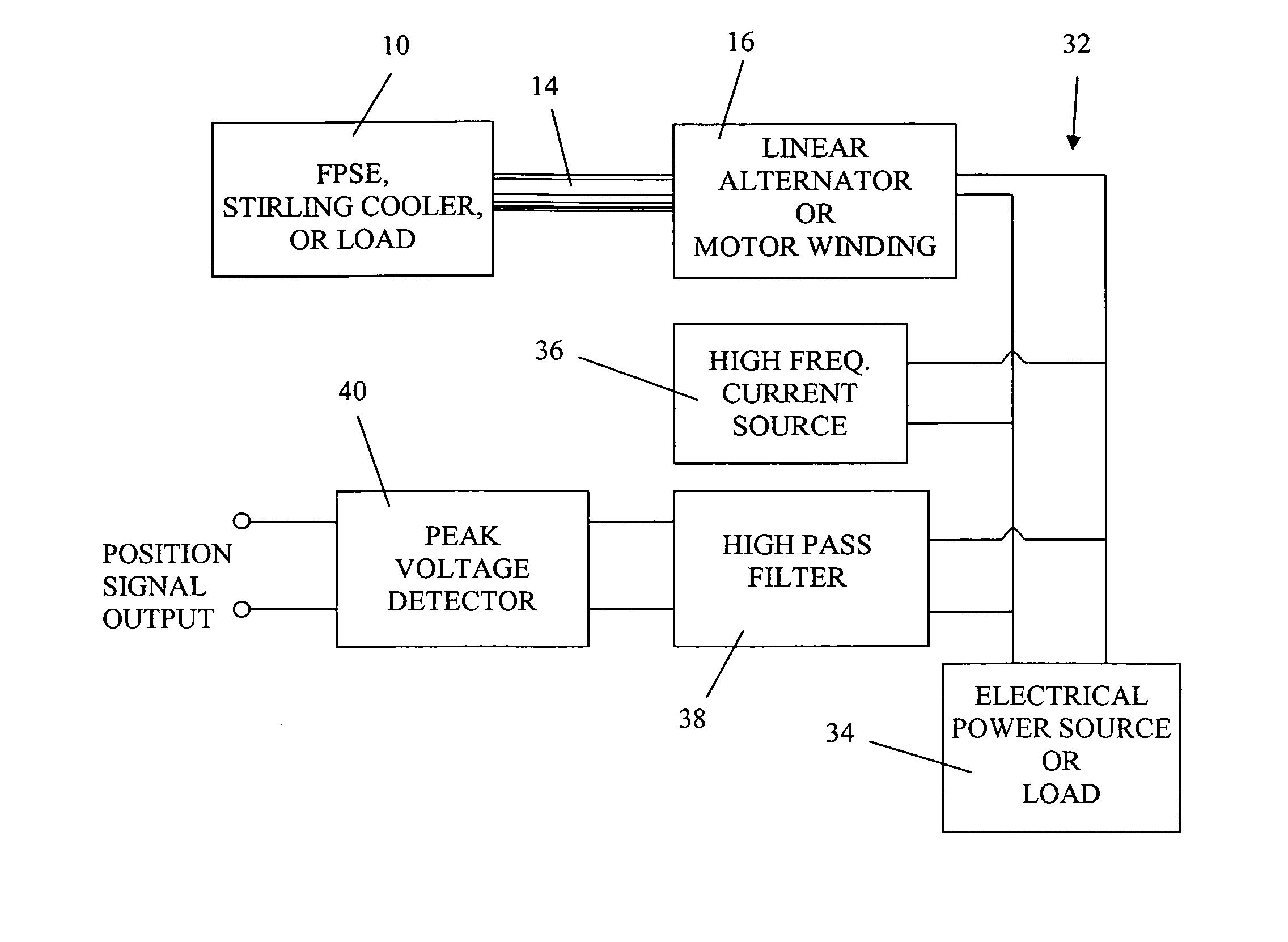
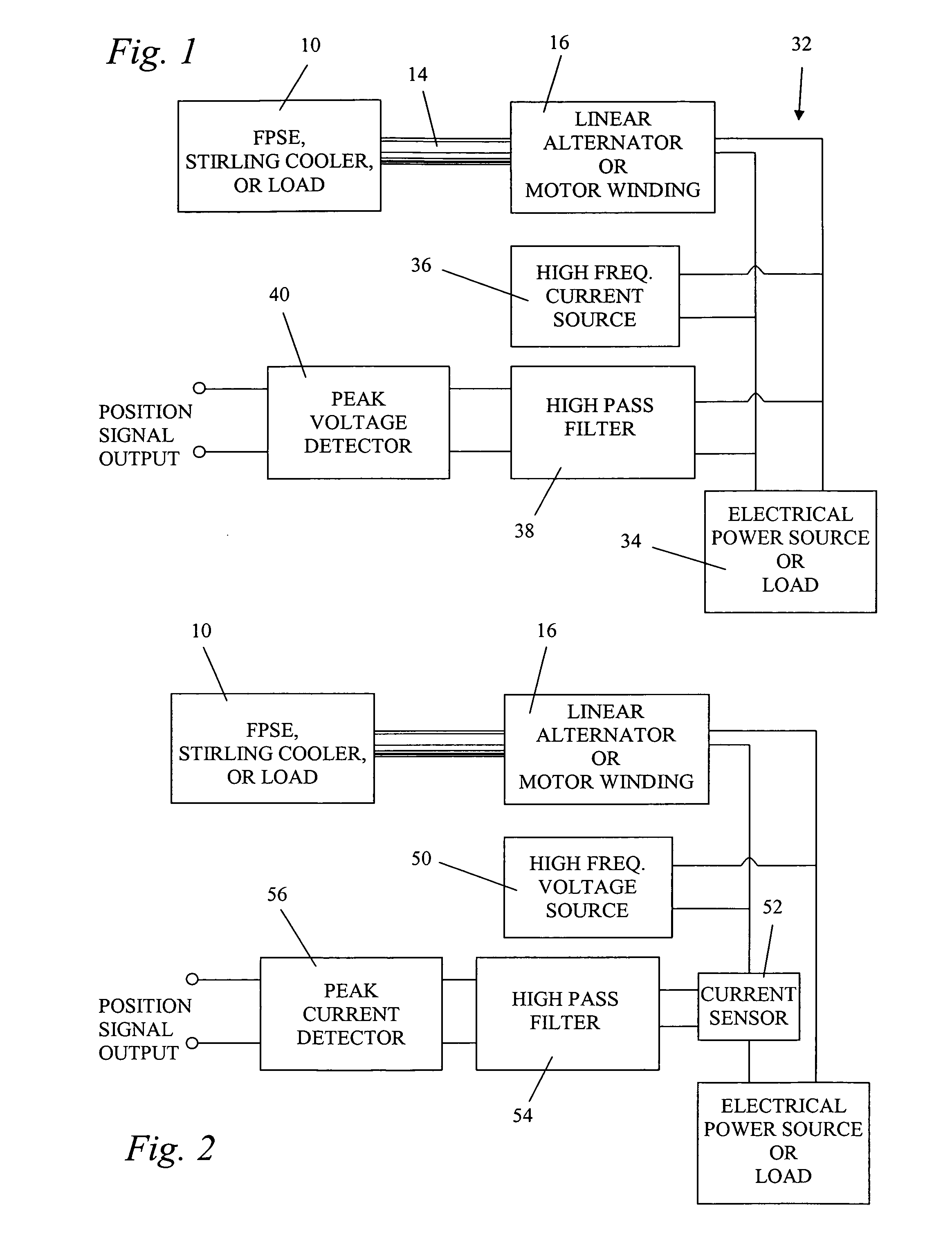
[0013]The invention is a method and circuit for sensing the instantaneous position of a piston of a free piston Stirling engine, a free piston Stirling cooler, a linear compressor or other prime mover or mechanical load mechanically connected to the reciprocating member of an electric linear electric motor or alternator. A linear electric motor or alternator has a winding electrically connected in a winding circuit to either a source of electrical driving power or to an electrical load. The reciprocating member is reciprocatable at an operating frequency of reciprocation. The invention applies a high frequency, alternating, electrical signal to the winding. The winding voltage or current is filtered by passing signals at the high frequency and blocking signals at the operating frequency of the electric linear motor or alternator. The instantaneous peak value of the filtered signal as a function of time is detected to provide an output signal that is substantially a linear function of the instantaneous piston position as a function of time and is independent of the high power currents or voltages at the low operating frequency of reciprocation

Problems solved by technology

That transducer has the disadvantage that it adds weight and additional expense, requires mounting and occupies space within the machine and is an additional component that can fail.
This prior art detection system has the disadvantage that it requires measurement of the inductance of the alternator winding, the AC resistance and the back emf constant (also known as the motor constant) α. The open circuit winding voltage is proportional to the piston velocity and the back emf constant α is the proportionality constant that relates open circuit winding voltage to piston velocity.
Consequently, measurements of stroke amplitude using the method of U.S. Pat. No. 5,342,176 exhibit errors resulting from drift of the detected stroke amplitude as a function of temperature.

Method used


Image

  • Detection of the instantaneous position of a linearly reciprocating member using high frequency injection
  • Detection of the instantaneous position of a linearly reciprocating member using high frequency injection
  • Detection of the instantaneous position of a linearly reciprocating member using high frequency injection

Examples


Embodiment Construction

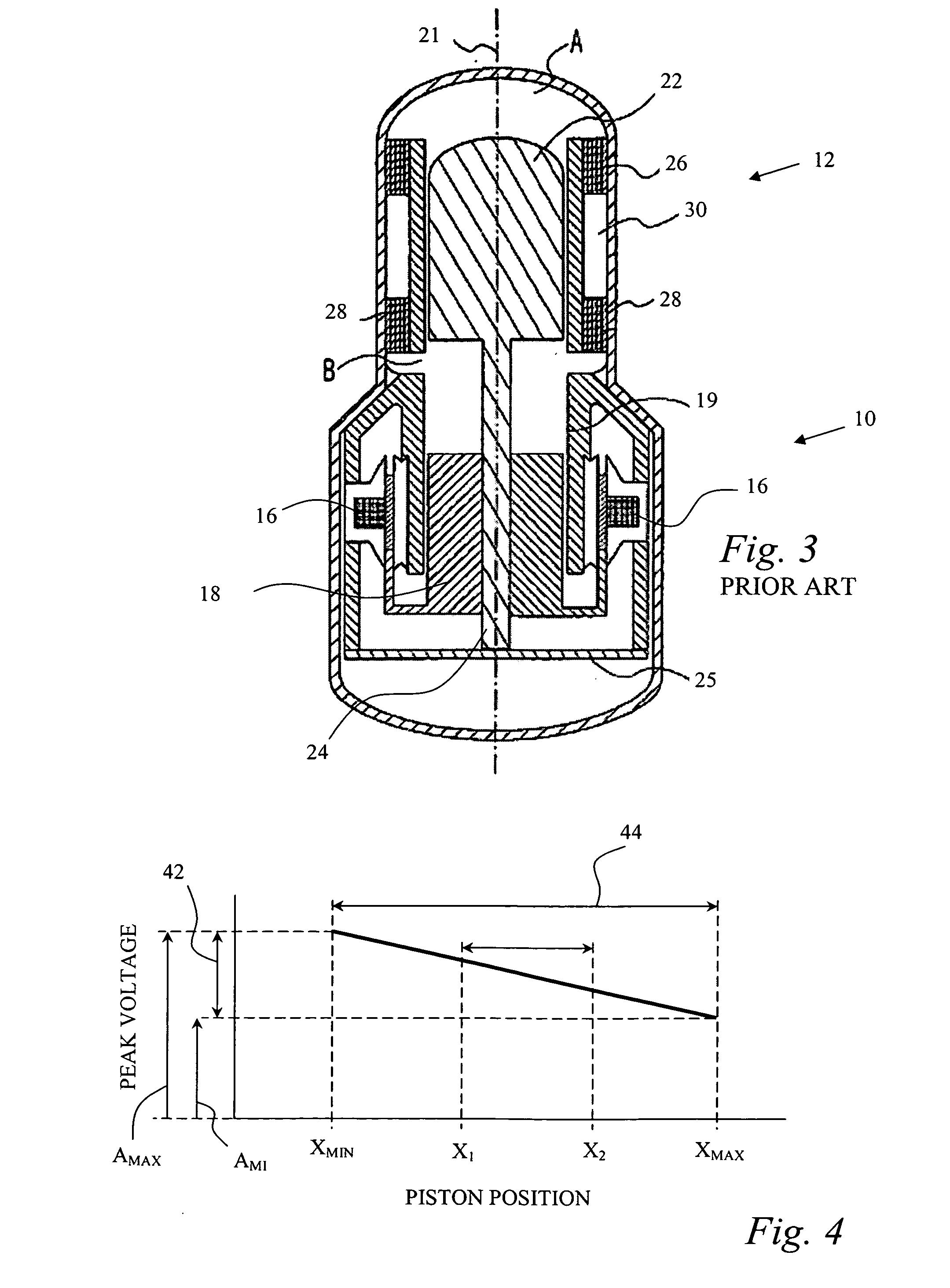
[0019]The block diagram of FIG. 1 diagrammatically illustrates a free piston Stirling machine or a compressor 10 mechanically connected to the reciprocating member of a linear electric motor / alternator through a symbolic connecting rod 14. A representative, prior art implementation of these structures is illustrated in FIG. 3. The Stirling machine and the linear motor / alternator are mechanically integrated to some extent so they do not appear in FIG. 3 in a simple side by side arrangement. The linear electric motor / alternator 10 has an armature winding 16. The power piston 18 of the Stirling machine 12 reciprocates axially within a cylinder 19 at an operating frequency of reciprocation and is rigidly connected to and supports a series of permanent magnets 20 which, therefore, also reciprocate axially (along axis 21) within the armature winding 16 at the operating frequency of reciprocation. Consequently, because the piston 18 and the magnets and their supports are integrated togethe...


PUM


Abstract

A piston position sensing circuit for sensing the instantaneous position of a piston of a free piston Stirling machine or a compressor mechanically connected to a reciprocating member of a linear electric motor or alternator. A source of a high frequency, alternating, electrical signal applies a high frequency signal to the winding circuit of the linear alternator or motor. A filter circuit is connected to the winding circuit and passes electrical signals at the frequency of the high frequency source and blocks signals at the operating frequency of reciprocation. A peak detector circuit is connected to the filter circuit and detects the peak of the filter circuit output signal to provide an instantaneous peak magnitude that is proportional to the instantaneous piston position.

Description

BACKGROUND OF THE INVENTION[0001]1. Field of the Invention[0002]This invention relates generally to free piston Stirling engines, free piston Stirling heat pumps or coolers, compressors or other mechanical loads drivingly connected to a linear alternator or linear motor and more particularly relates to a circuit for sensing, and for providing a signal that is proportional to, the instantaneous position of the reciprocating piston of the Stirling engine, cooler or heat pump or compressor and the instantaneous position of the reciprocating member of the linear alternator or motor.[0003]2. Description of the Related Art[0004]Stirling machines have been known for nearly two centuries but in recent decades have been the subject of considerable development because of advantages they offer. In a Stirling machine, a working gas is confined in a working space comprised of an expansion space and a compression space. The working gas is alternately expanded and compressed in order to either do ...

Claims


Application Information

Patent Timeline
Patent Type & Authority Applications(United States)
IPC IPC(8): G01B7/14
CPCF02G1/045F02G2275/20G01D5/243F04B2201/0201G01D5/202F04B35/045
Inventor HOLLIDAY, EZEKIEL S.
Owner SUNPOWER
Learn More