Photoelectric conversion apparatus and image sensing system

a conversion apparatus and photoelectric technology, applied in the field of photoelectric conversion apparatus and image sensing system, can solve the problems of reducing the operation speed, affecting the high speed reading, and affecting the gain of differential amplifiers, so as to achieve the effect of suppressing the reading speed decreas

Inactive Publication Date: 2008-03-13
CANON KK
View PDF31 Cites 58 Cited by
  • Summary
  • Abstract
  • Description
  • Claims
  • Application Information

AI Technical Summary

Benefits of technology

[0012]Therefore, the present invention provides a configuration including a full

Problems solved by technology

In a conventional photoelectric conversion apparatus, an electromagnetic field noise emanating from the outside generates a noise voltage in wiring in the apparatus, which becomes a noise output.
This decrease in speed significantly affects the high speed reading.
In this way, the error regarding the gain of the differential amplifier depends on the parasitic capacitance of the horizontal common outpu

Method used


Image

  • Photoelectric conversion apparatus and image sensing system
  • Photoelectric conversion apparatus and image sensing system
  • Photoelectric conversion apparatus and image sensing system

Examples


first embodiment

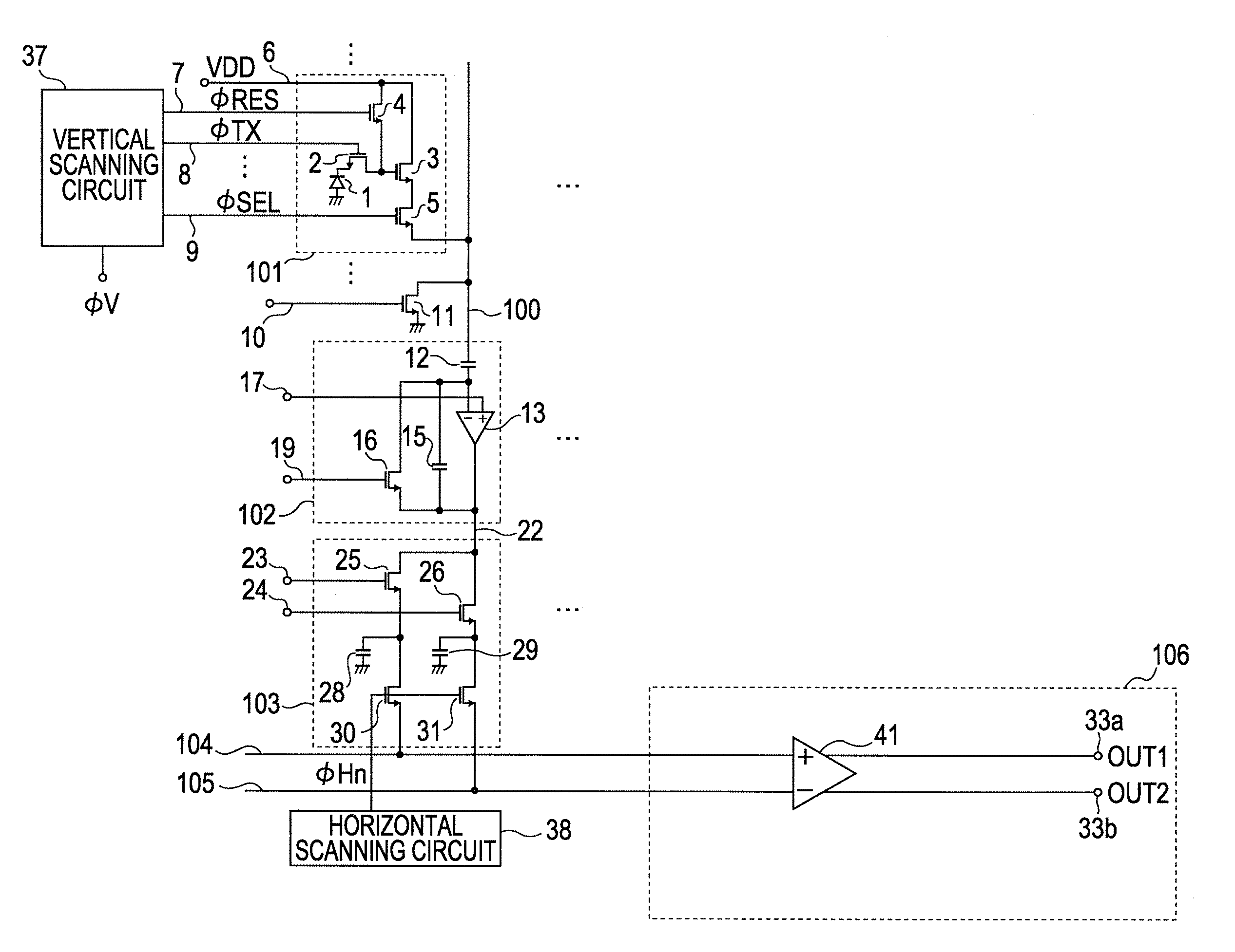
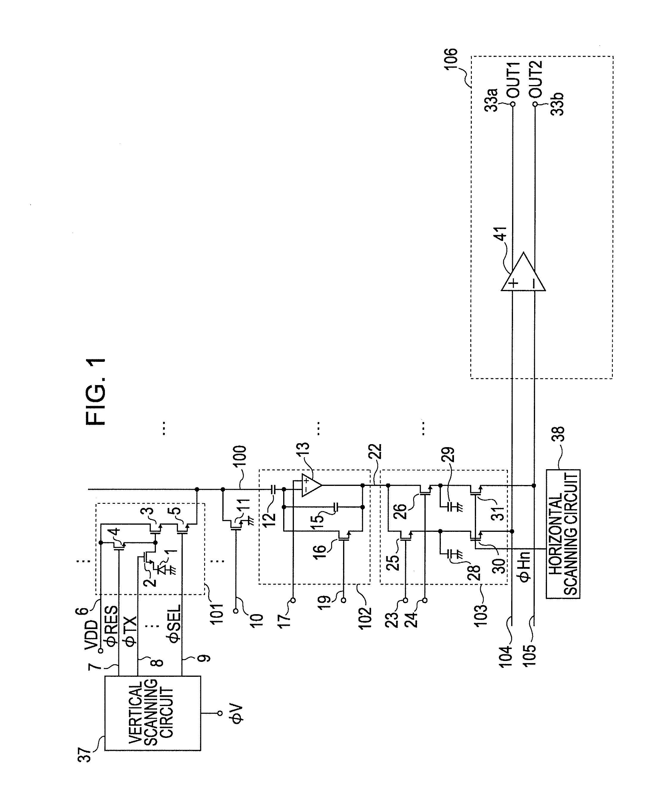
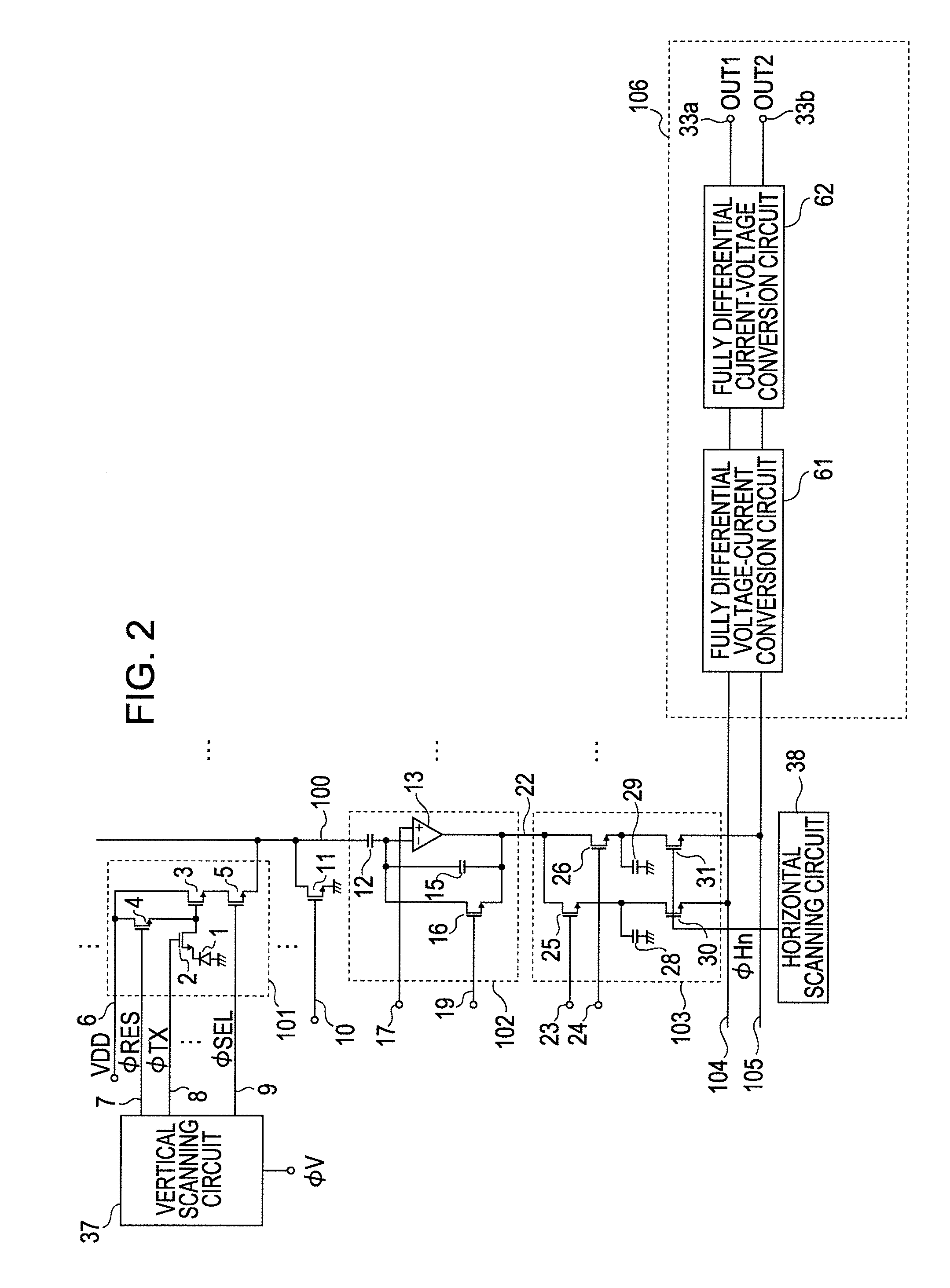
[0039]FIG. 2 illustrates a photoelectric conversion apparatus according to a first embodiment of the present invention. Components having similar functions to those in FIG. 1 are denoted by the same reference numerals and detailed descriptions thereof will be omitted. According to the present embodiment, a fully differential amplifier is used as a configuration included in an output circuit unit, no feedback path is provided between an input terminal and an output terminal in the configuration. When an entire amplifier is observed, a plurality of input terminals including a first input terminal and a second input terminal and a plurality of output terminals including a first output terminal and a second output terminal are provided.

[0040]To be more specific, the output circuit unit 106 includes a voltage-current conversion circuit 61 and a current-voltage conversion circuit 62 to which an output of the voltage-current conversion circuit is transmitted. The voltage-current conversion...

second embodiment

[0056]FIG. 4 illustrates a photoelectric conversion apparatus according to a second embodiment of the present invention. Components having similar functions to those in FIGS. 1 to 3 are denoted by the same reference numerals and detailed descriptions thereof will be omitted. A difference from the first embodiment resides in a circuit format of the output circuit unit 106. In the photoelectric conversion apparatus according to the first embodiment, depending on the characteristic variation of the component elements due to the manufacturing variation, the common-mode variation that the circuit itself originally has may appear in some cases. More specifically, the output voltages of the output terminals 33a and 33b when no voltage difference exists between the horizontal common output lines 104 and 105 and the optical signal is not supplied may have a variation for each photoelectric conversion apparatus in some cases. For example, when the resistance value R2 of the resistors 65a and ...

third embodiment

[0065]FIG. 6 illustrates a photoelectric conversion apparatus according to a third embodiment of the present invention. Components having similar functions to those in the above-described embodiments are denoted by the same reference numerals and detailed descriptions thereof will be omitted. Components having similar functions to those of the configurations in the drawings according to the above-described embodiments are denoted by the same reference numerals and detailed descriptions thereof will be omitted. According to the present embodiment, it is characterized in that after the signal output from the pixel area is temporarily held in the hold capacitor, before the signal is transferred to the signal path for transferring the signal to the amplifier, blocks are formed for a plurality of hold capacitors. In other words, it can be said that a block formation area is provided for connecting between the switches for transferring the signal from the hold capacitor to the horizontal ...


PUM


Abstract

To provide a configuration including a fully differential amplifier in which decrease in a reading speed can be suppressed. A photoelectric conversion apparatus according to the present invention includes a pixel area where a plurality of pixels are arranged; an amplifier configured to amplify a signal from the pixel area; a plurality of signal paths for transmitting the signals from the pixel area to the amplifier. The amplifier is a fully differential amplifier which includes a plurality of input terminals including a first input terminal and a second input terminal to which the signals from the plurality of signal paths are supplied and a plurality of output terminals including a first output terminal and a second output terminal and the input terminals and the output terminals have no feedback path provided therebetween.

Description

BACKGROUND OF THE INVENTION[0001]1. Field of the Invention[0002]The present invention relates to a photoelectric conversion apparatus widely used in particularly a video camera, a digital still camera, and an image input apparatus for an image scanner. In particular, the invention relates to an output circuit of the photoelectric conversion apparatus.[0003]2. Description of the Related Art[0004]In a conventional photoelectric conversion apparatus, an electromagnetic field noise emanating from the outside generates a noise voltage in wiring in the apparatus, which becomes a noise output. Thus, an S / N (signal-to-noise) ratio is degraded. Japanese Patent Laid-Open No. 2004-186790 discloses a configuration of a differential amplifier provided to a horizontal common output line. In the differential amplifier, a differential output between a signal level (S) and a reset level (N) is output. FIG. 11 illustrates a photoelectric conversion apparatus disclosed in Japanese Patent Laid-Open No....

Claims


Application Information

Patent Timeline
IPC IPC(8): H04N5/335H03F3/45H04N5/374
CPCH03F3/08H03F3/45183H03F3/45475H03F2200/78H03F2203/45134H04N5/378H03F2203/45392H03F2203/45641H03F2203/45732H04N5/3575H04N5/37213H03F2203/45356H04N25/616H04N25/713H04N25/75
Inventor FUJIMURA, MASARUOGURA, MASANORIKOIZUMI, TORU
Owner CANON KK
Why Eureka
Try Eureka