Optical interference filter that performs excellent color separation, and liquid crystal display, electroluminescence display and projection display apparatus having the optical interference filter

a color separation and optical interference technology, applied in the field of optical interference filters, can solve the problems of increasing cost, manufacturing facilities cannot be used, and the effect of deteriorating the function of color separation due to the oblique light can be suppressed

Inactive Publication Date: 2008-03-13
PANASONIC CORP
View PDF5 Cites 42 Cited by
  • Summary
  • Abstract
  • Description
  • Claims
  • Application Information

AI Technical Summary

Benefits of technology

[0016]In view of the above-described problems, a first object of the present invention is to provide an optical interference filter that prevents the color mixing caused by oblique light being transmitted through two transmission regions whose filter characteristics are different from each other.
[0017]A second object of the present invention is to provide a liquid crystal display having the optical interference filter that prevents the color mixing caused by the oblique light.
[0018]A third object of the present invention is to provide an electroluminescence display having the optical interference filter that prevents the color mixing caused by the oblique light.

Problems solved by technology

Therefore, it is not effective to prevent the color mixing that occurs in the part that spans between the adjacent transmission regions.
If the light shielding material is attempted to be formed in the boundary region, namely, the part that spans between the adjacent transmission regions, the conventional manufacturing facilities cannot be used as they are, thereby increasing cost.
Also, from a technical standpoint, a secondary problem such as an increase of a distance between pixels may arise.

Method used


Image

  • Optical interference filter that performs excellent color separation, and liquid crystal display, electroluminescence display and projection display apparatus having the optical interference filter
  • Optical interference filter that performs excellent color separation, and liquid crystal display, electroluminescence display and projection display apparatus having the optical interference filter
  • Optical interference filter that performs excellent color separation, and liquid crystal display, electroluminescence display and projection display apparatus having the optical interference filter

Examples


first embodiment

1. Structure

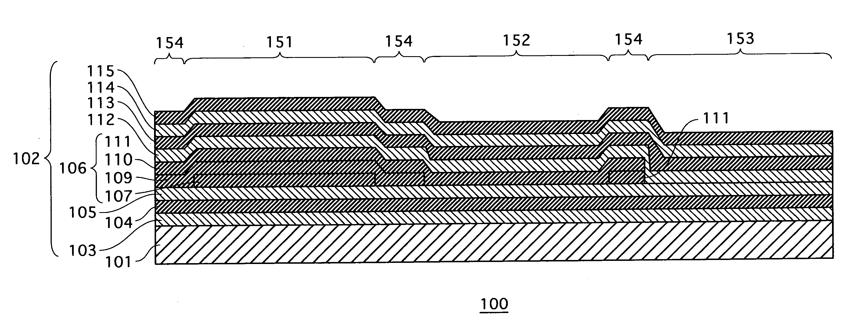
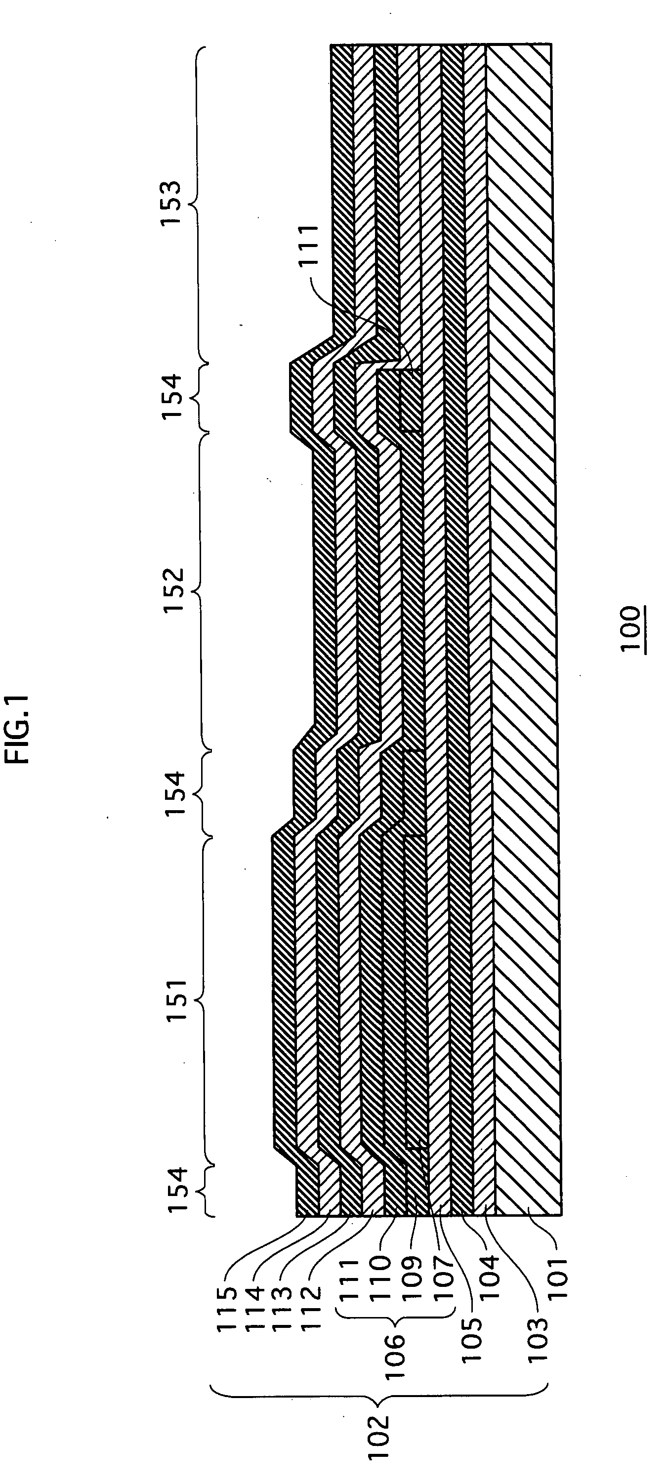
[0052]FIG. 1 is a local sectional view of an optical interference filter 100 according to the first embodiment of the present invention.

[0053]The optical interference filter 100 separates colors of red, green, and blue, and is formed such that, on a transparent substrate 101, a first high refractive index layer 103, a first low refractive index layer 104, a second high refractive index layer 105, a low refractive index composite layer 106, a third high refractive index layer 112, a second low refractive index layer 113, a fourth high refractive index layer 114, and a third low refractive index layer 115 are laminated on each other in the stated order. Also, the optical interference filter 100 is different from conventional optical interference filters that each include low refractive index layers and high refractive index layers simply laminated on each other. Instead, in the optical interference filter 100, the optical film thickness of the low refractive index composit...

second embodiment

[0123]FIG. 5A is a diagram showing an optical interference filter 200 according to a second embodiment of the present invention.

[0124]The optical interference filter 200 is a multilayer type optical interference color filter formed with use of the photonic crystal technique, and separates colors of red, green, and blue, as is the case with the optical interference filter 100.

[0125]The difference between the optical interference filters 100 and 200 is that the optical interference filter 100 includes only one spacer layer for the color separation while the optical interference filter 200 of the second embodiment includes two spacer layers and the optical film thickness of high refractive index layers and low refractive index layers excluding the above-described two spacer layers is substantially the same.

[0126]In other words, the optical interference filter 200 has the same structure as the optical interference filter 100 except the one spacer layer that has been added newly. Also, t...


PUM

PropertyMeasurementUnit
thicknessaaaaaaaaaa
thicknessaaaaaaaaaa
thicknessaaaaaaaaaa

Abstract

An optical interference filter whose major component is a film member. The film member includes a plurality of window regions arranged discretely in a surface direction selectively transmit, using an effect of optical interference, light having a waveband that substantially belongs to a visible spectrum, the plurality of window regions being arranged discretely in the surface direction, and one or more boundary regions selectively transmit, using the effect of the optical interference, light having a waveband that substantially belongs to an invisible spectrum excluding the visible spectrum, the one or more the boundary regions being located between adjacent window regions.

Description

BACKGROUND OF THE INVENTION[0001](1) Field of the Invention[0002]The present invention relates to an optical interference filter used for a display device such as a liquid crystal display or a plasma display, and more particularly to a technique to improve efficiency of color separation.[0003](2) Description of the Related Art[0004]In recent years, a multilayer optical interference filter has been prevalent as a color filter that can offer a stable characteristic with respect to heat resistance and light resistance while withstanding chemicals such as acid and alkaline. The multilayer optical interference filter realizes the performance of separating colors including red, green, blue and so on by the interference effect of laminated films, which are formed by thin films of inorganic compounds being laminated on each other.[0005]FIG. 10 shows the structure of such a conventional color filter as described above.[0006]This color filter is formed such that Titanium Dioxide (TiO2) which ...

Claims


Application Information

Patent Timeline
Patent Type & Authority Applications(United States)
IPC IPC(8): G02B1/10G02F1/1335H01J1/62
CPCG02B5/285H05B33/22H01L27/322G02F2001/133521G02F1/133521H10K59/38
Inventor INABA, YUICHIYAMAGUCHI, TAKUMIUEDA, DAISUKE
Owner PANASONIC CORP
Why Eureka
Try Eureka