Transmitting Device for Free-Space Optical Transmission

a transmission device and free-space technology, applied in electromagnetic transmission, transmission, close-range type systems, etc., can solve the problems of difficult implementation of the approach, the inability to address the question of the means for delivering the signals to be transmitted to the lamp in a manner satisfactory for all applications, and the use of two separate wirings is obviously more expensiv

Inactive Publication Date: 2008-03-13
ZXTALK ASSETAB
View PDF21 Cites 48 Cited by
  • Summary
  • Abstract
  • Description
  • Claims
  • Application Information

AI Technical Summary

Benefits of technology

[0025] The article of E. Biglieri entitled “Coding and Modulation for a Horrible Channel” published in the IEEE Communications Magazine, Vol. 41, No. 5, May 2003, at the pages 92 to 98, teaches us that, for transmission via power distribution lines, the modulation of a single carrier is often not a good technical solution. Consequently, a device of the invention may be characterized in that the receiving set for transmission via power distribution lines uses a modulation method using several carriers or a spread spectrum technique. For instance, modulation method using several carriers, such as the orthogonal frequency-domain multiplex (also referred to as OFDM), may give good results.

Problems solved by technology

The above-mentioned application of Martin R. Dachs relates to a device of this type, though this approach is difficult to implement because firstly the electrical characteristics of discharge lamps are such that a control device according to this approach is complex (or has a low efficiency), and secondly discharge lamps are generally not designed to be submitted to a current having a d.c. component.
According to the prior art, the question of the means for delivering the signals to be transmitted to the lamp is not addressed in a manner satisfactory for all applications, since the use of two separate wirings is obviously more expensive than a classical wiring for luminaires only intended for lighting.

Method used


Image

  • Transmitting Device for Free-Space Optical Transmission
  • Transmitting Device for Free-Space Optical Transmission

Examples


Embodiment Construction

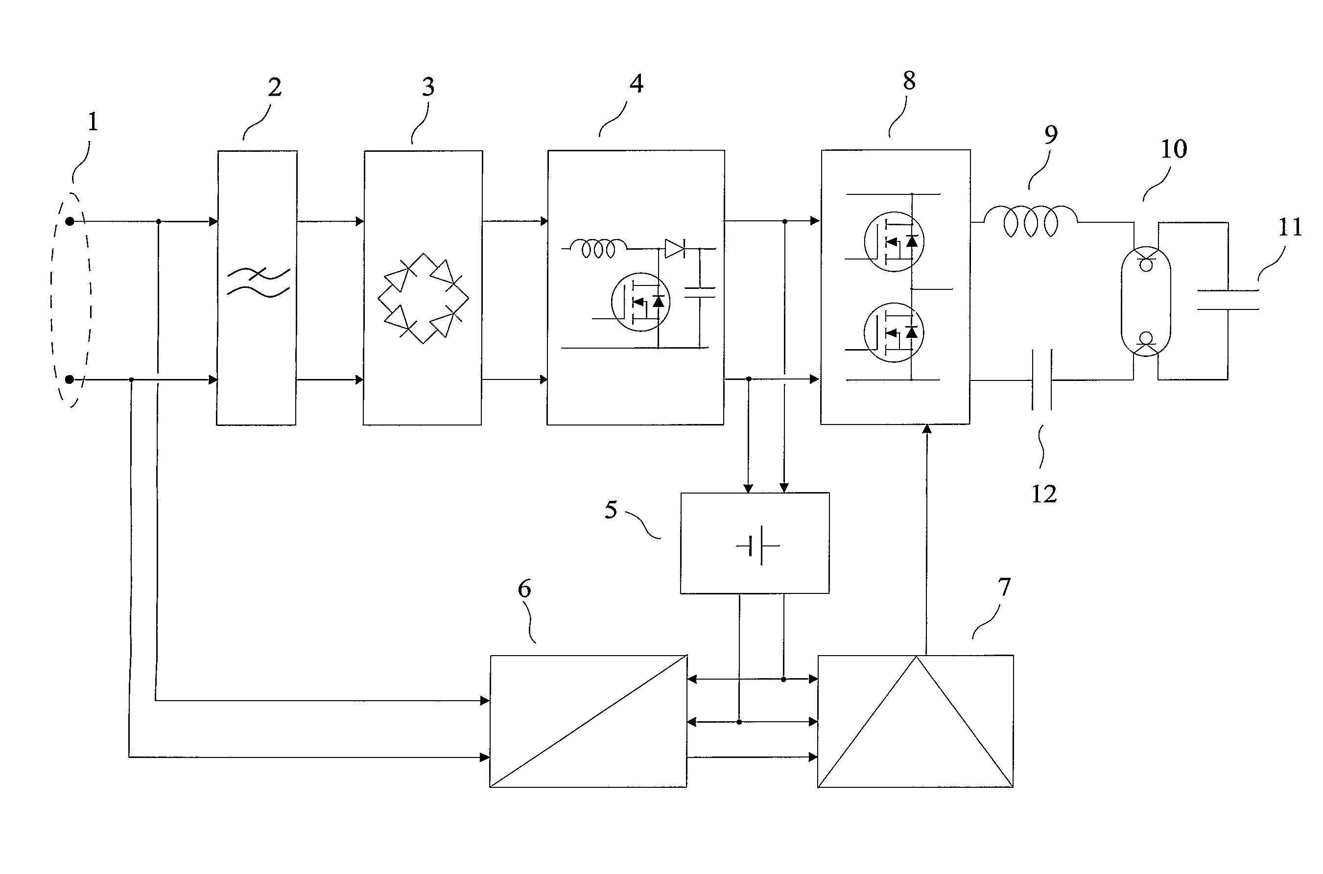
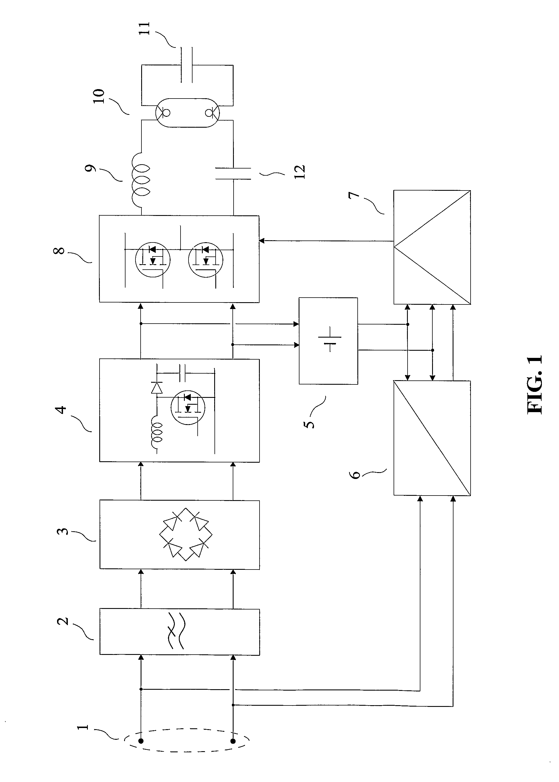
[0017] The purpose of the invention is a transmitting device for free-space optical transmission which does not require a separate wiring for delivering its input signals, without the limitations of known methods and devices.

[0018] The invention is about a transmitting device for free-space optical transmission, characterized in that: [0019] firstly it comprises one or several discharge lamps used as light source for transmission, [0020] secondly it comprises a receiving set for transmission via power distribution lines, capable of delivering “demodulated signals” at its output, the “demodulated signals” being obtained from a demodulation of signals appearing at the terminals allowing to power-feed the transmitting device, [0021] thirdly the “demodulated signals” are applied to the input of a control device which modulates the light produced by said one or several discharge lamps as a function of the “demodulated signals”.

[0022] The receiving set for transmission via power distrib...


PUM


Abstract

Transmitting device for free-space optical transmission. The invention relates to a transmitting device for transmission through space, using electromagnetic waves of the infrared and / or visible and / or ultraviolet bands produced by one or several discharge lamps. The device is connected by its input terminals (1) to an a.c. energy distribution system. A mains filter (2) reduces the conducted electromagnetic disturbances produced by the power circuits comprising a rectifier (3), a power-factor-correction circuit (4), a low-voltage power supply (5) and an inverter (8). The inverter (8) is connected to a series inductor (9) connected in series with a hot-cathode fluorescent lamp (10) and a capacitor (12), a parallel capacitor (11) allowing an optimal start of the lamp. A receiving set for transmission via power distribution lines (6) delivers “demodulated signals” applied to the control circuitry (7) which controls the state of the switches of the inverter (8). The light produced is modulated as a function of the “demodulated signals”.

Description

FIELD OF THE INVENTION [0001] The invention relates to a transmitting device for transmission through space, using electromagnetic waves of the infrared and / or visible and / or ultraviolet bands produced by one or several discharge lamps. [0002] The French patent application number 0409939 of 20 Sep. 2004, entitled “Dispositif d'émission pour la transmission optique en espace libre” is incorporated by reference. PRIOR ART [0003] In the following, the word “light” will designate an electromagnetic radiation which may comprise visible light and / or infrared light and / or ultraviolet light. In the following, the wording “discharge lamp” will designate a discharge lamp of any type. This lamp may for instance be a low-pressure discharge lamp, for instance a mercury vapour fluorescent tube, or a compact fluorescent lamp, or a sodium vapour lamp, etc. This lamp may for instance be a high-pressure discharge lamp, for instance a metal iodide lamp. [0004] The idea of using discharge lamps for opt...

Claims


Application Information

Patent Timeline
Patent Type & Authority Applications(United States)
IPC IPC(8): H04B10/10H05B41/26H04B10/114H04B10/116
CPCH04B10/116H04B10/1149H04B10/11H05B41/26H04B10/00
Inventor BROYDE, FREDERICCLAVELIER, EVELYNE
Owner ZXTALK ASSETAB
Why Eureka
Try Eureka