
Memory controlling method

Inactive Publication Date: 2008-03-13
NATIONAL CHUNG CHENG UNIV
View PDF6 Cites 8 Cited by
  • Summary
  • Abstract
  • Description
  • Claims
  • Application Information

AI Technical Summary

Benefits of technology

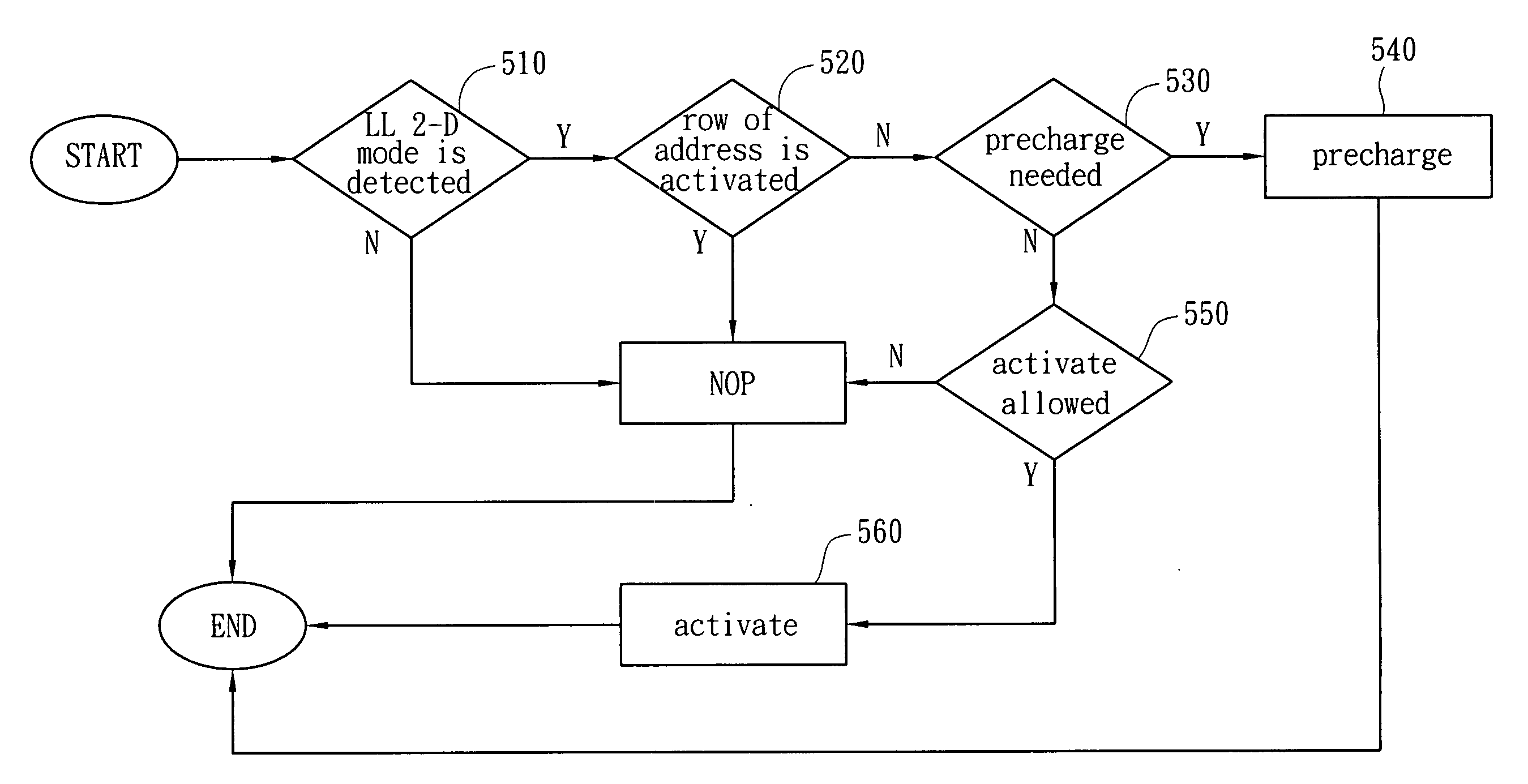
[0009]It is another objective of the present invention to provide a memory controlling method, including burst terminates burst (BTB) and anticipative row activation (ARA) in order to reduce the latency of the memory accessing.
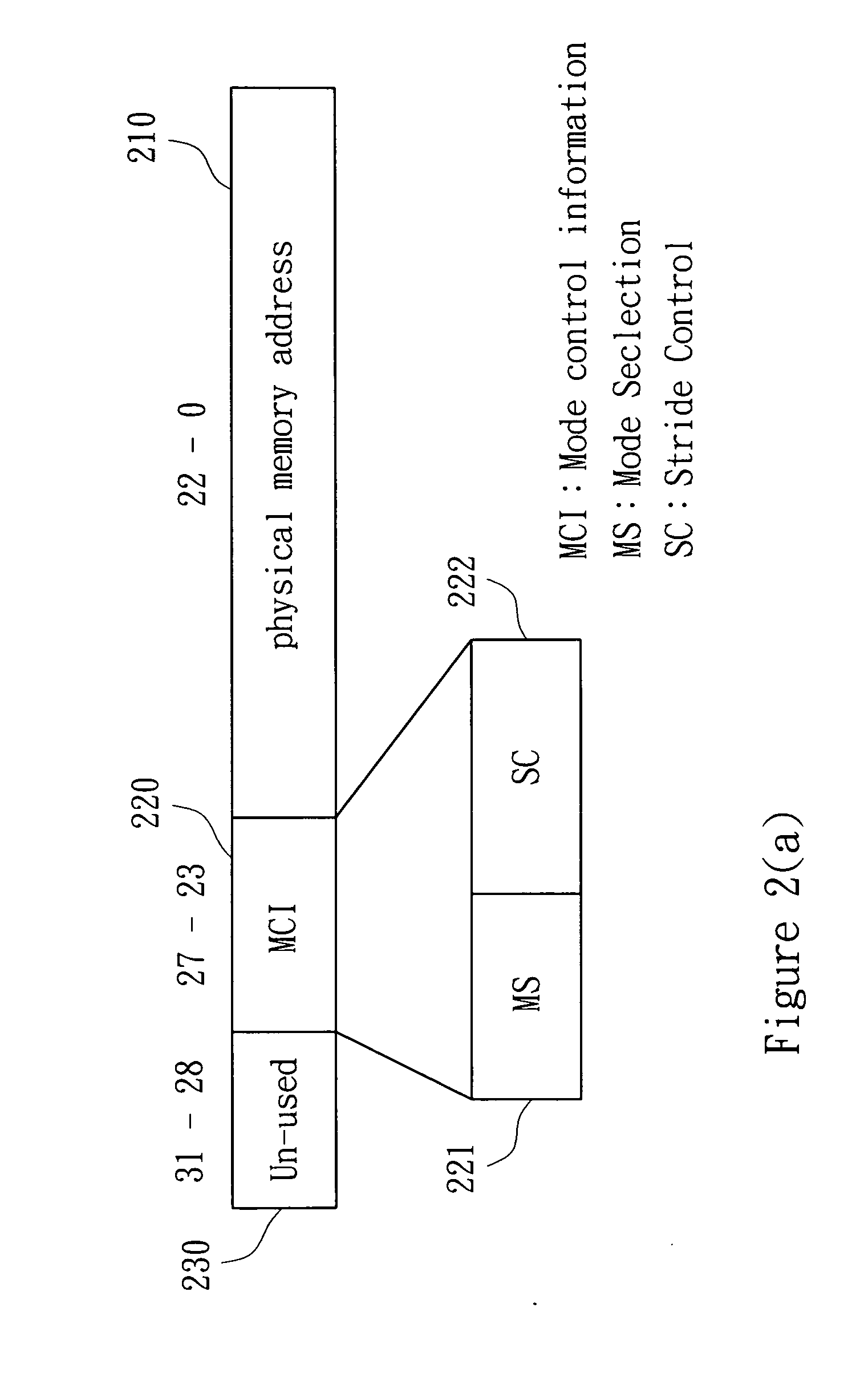
[0010]According to the aforementioned objectives of the present invention, a memory controlling method is provided. In accordance with one embodiment of the present invention, allocating a memory mapped space larger than physical memory size for getting additional addressing bits used to transfer the mode control information (MCI), and using the mode control information to setup a stride value and a sequential data length for a 2-dimensional (2-D) data access. Then, an embedded address generator is used to obtain the non-sequential addresses of a 2-dimensional data accessing in advance. Then we can overcome the communication restriction from AHB interface and reduce the latency, in order to enhance the memory access efficiency and offer the access expansion mode.
[0011]According to another objective of the present invention, a memory controlling method is disclosed. In one embodiment of the present invention, the continuous data length and the succeeding non-continuous accessing address is known in advance, this invention proposes a memory controlling method, Burst Terminates Burst (BTB), which issues the SDRAM read / write command of impending non-continuous access to terminate the current burst transfer to reduce the latency of the non-continuous data, and then raise the data accessing efficiency in a fixed period of time.
[0012]The present invention proposes an anticipative row activating (ARA) method, storing the image / pixel data in the order of interlaced banks with sequential rows. In other words, this kind of memory organization limits the 2-dimensional data access into two situations. First, the next non-continuous data lie in the present memory row, and we can utilize the accessing method of BTB in order to reduce latency in this situation. Second, the next non-continuous data lie in the memory row of a different bank, in this case, this invention utilizes the waiting period for the SDRAM commands to activate the memory row in which the next non-sequential data located in advance. This fact reduces the latency of the accesses switched over different memory banks and rows. According to the above-mentioned contents, this invention has the following advantages:
[0013]1. This invention applies to the advanced high-performance bus as a scheme to optimize the accessing efficiency in order to reduce the latency when the accessing addresses are non-continuous.
[0014]2. This invention utilizes the controlling of ARA to reduce the latency induced by the frequent switches of memory bank / row.

Problems solved by technology

However, when SDRAM accesses memory, the latency is very long.
Therefore when accessing the non-continuous address, the data can not be outputted continuously, meaning that each time when accessing a non-continuous address, there will be CAS latency at least that causes a low access rate.
Therefore, an optimizing scheme to enhance memory access efficiency with SDRAM traits is a problem in the known technique.
In other words, this kind of memory organization limits the 2-dimensional data access into two situations.

Method used


Image

  • Memory controlling method
  • Memory controlling method
  • Memory controlling method

Examples


Embodiment Construction

[0025]Reference will now be made in detail to the present preferred embodiments of the invention, examples of which are illustrated in the accompanying drawings. Wherever possible, the same reference numbers are used in the drawings and the description to refer to the same or like parts.

[0026]While the specification concludes with claims defining the features of the invention that are regarded as novel, it is believed that the invention will be better understood from a consideration of the following description in conjunction with the figures, in which like reference numerals are carried forward.

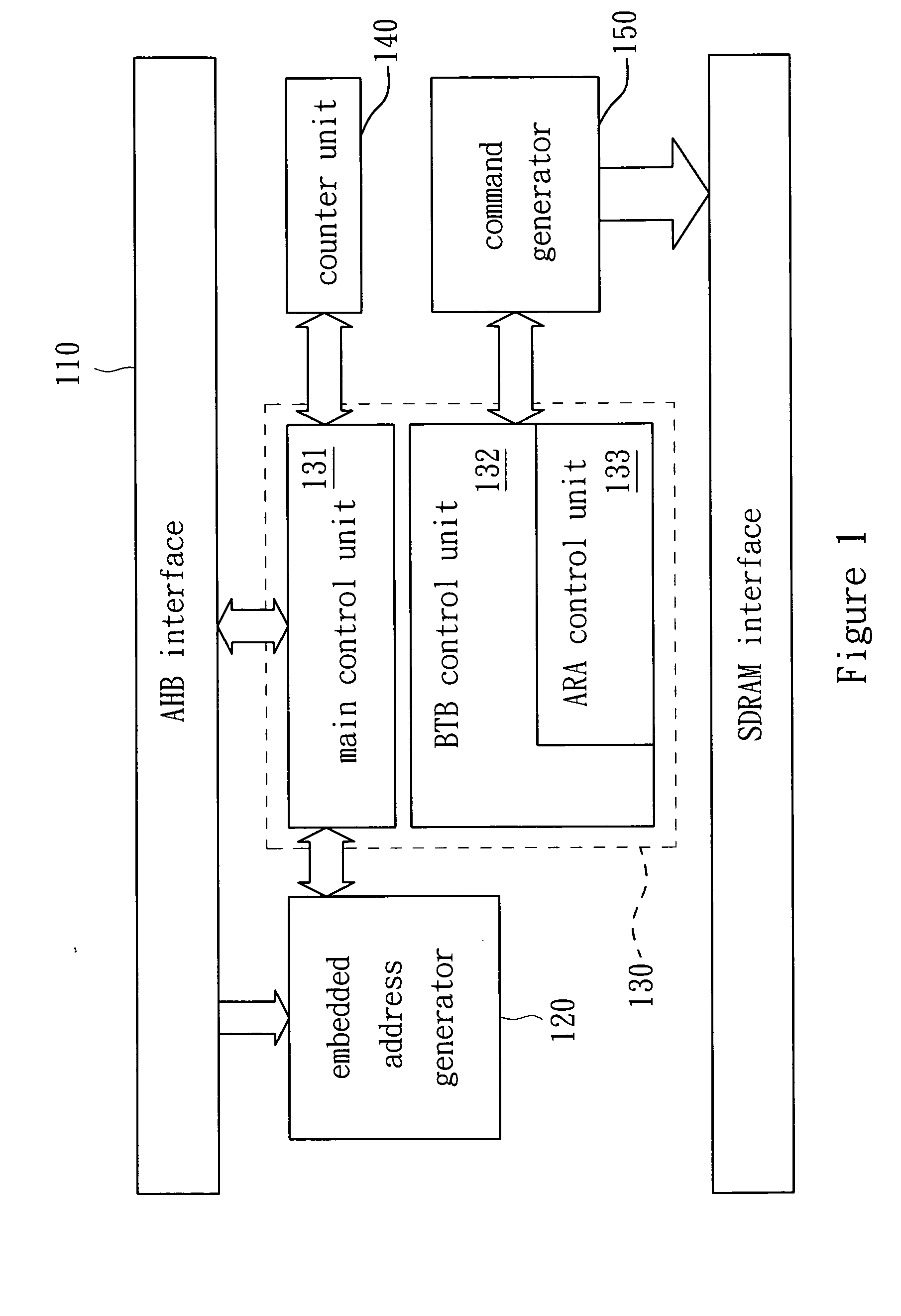
[0027]Refer to FIG. 1. FIG. 1 shows a schematic block diagram of SDRAM controller of the preferred embodiment of the present invention. According to the address and controlling information, the AHB interface 110 accepts the AHB master accessing requests to determine whether EAG 120 is enabled or not. If it is enabled, it means low latency accessing mode. If it is not enabled, it is the gener...


PUM


Abstract

A method for memory controlling is disclosed. It includes an embedded address generator and a controlling scheme of burst terminates burst, which could erase the latency caused by bus interface during the access of non-continuous addresses. Moreover, it includes a controlling scheme of anticipative row activating, which could reduce the latency across different rows of memory by data access. The method could improve the access efficiency and power consumption of memory.

Description

BACKGROUND[0001]1. Field of Invention[0002]The present invention relates to a memory controlling method. More particularly, the present invention relates to a memory controlling method with an advanced high-performance bus interface.[0003]2. Description of Related Art[0004]In the digital signal processing systems or media video systems, a large amount of memory is needed to store the data the system requires. Therefore, SDRAM is extensively used in this kind of system because of its high capacity and low cost quality. However, when SDRAM accesses memory, the latency is very long.[0005]Several SDRAM controllers have been proposed to make efficient use of the SDRAM. One is to schedule the requests of data access, and allow the accesses in the same row of a specific bank can be performed together as most as possible. This method reduces the switching frequency of transfers between different rows. Another approach focuses on data arrangement in memory. By analysis of data access for spe...

Claims


Application Information

Patent Timeline
IPC IPC(8): G06F12/06G06F12/00
CPCG06F12/0207Y02B60/1228Y02B60/1225G06F13/161Y02D10/00
Inventor GUO, JIUN-INCHIEN, CHIH-TAHUANG, CHIA-JUI
Owner NATIONAL CHUNG CHENG UNIV
Learn More