Radio frequency controlled central vacuum endfitting

a technology of vacuum cleaner and vacuum handle, which is applied in the direction of suction handle, suction hose, suction cleaner, etc., can solve the problems of harkonen being in the means of stopping the vacuum cleaner and turning it off, and the wand being heavier, and achieves the effect of efficient and easy turning the central vacuum cleaner

Inactive Publication Date: 2008-03-20
HERRON ROY HOWARD JR
View PDF7 Cites 24 Cited by
  • Summary
  • Abstract
  • Description
  • Claims
  • Application Information

AI Technical Summary

Benefits of technology

[0013] It is an object of the present invention to produce a central vacuum RF controlled endfitting and handle that is cost effective to produce and easy to manufacture.
[0014] It is another object of the present invention to produce a RF controlled endfitting and handle that is easy to maintain and simple to install.
[0022] In addition to the improved switch of the present invention, the end fitting inserted into the wall valve is also equipped with an improved universal adapter. Prior art such as Moyer, Jr. et. al., implements a reversible rotably attached connector body, however with this type of end fitting, one could only use this type of end fitting with a limited type of wall valves. In addition, this type of universal end fitting is bulky, and there exists the potential for bending or breaking of the leads. The universal adapter of the present invention has individual contact pads that permits use with a variety of different wall valves, via these pads. In addition, the contact pads are spring loaded, thus these two features allow the end fitting of the present invention to maintain a snug fit regardless of what manufacturer's wall valve is used.
[0023] It is now virtually standard to have a switch built into the outlet so that insertion of the metal probe of a vacuum hose acts to contact a low voltage supply, which operates the central vacuum motor. The hose is then extended from the wall outlet to a simple handle / nozzle. The handle / nozzle may be operated with a brush, but the general idea is to suck the dirt into the system and into the central dust collector. The present invention allows the user to efficiently and easily turn the central vacuum cleaner on and off via RF. Although the use of RF for remote control is not new, one has yet to utilize it with a CV in a manner like the applicant. The present invention liberates the user of the need for these heavy flexible hoses, because the handle communicates with the end fitting via Radio Frequency, (hereinafter RF).

Problems solved by technology

In the prior art previously citied, Harkonen et al, there are present significant drawbacks.
The battery and sound generator combination occupy a significant volume within the handle of the wand, making the wand heavier, larger, and more unwieldy.
However, the end fitting, because its circuit does physical work by holding power to the relay, therefore power preservation is critical.
Perhaps the greatest difficulty with the method of Harkonen lies in the means for stopping the vacuum cleaner.
Further, items too large to pass conveniently through the tubing may be inadvertently sucked into the vacuum head, thereby turning it off.

Method used


Image

  • Radio frequency controlled central vacuum endfitting
  • Radio frequency controlled central vacuum endfitting
  • Radio frequency controlled central vacuum endfitting

Examples


Embodiment Construction

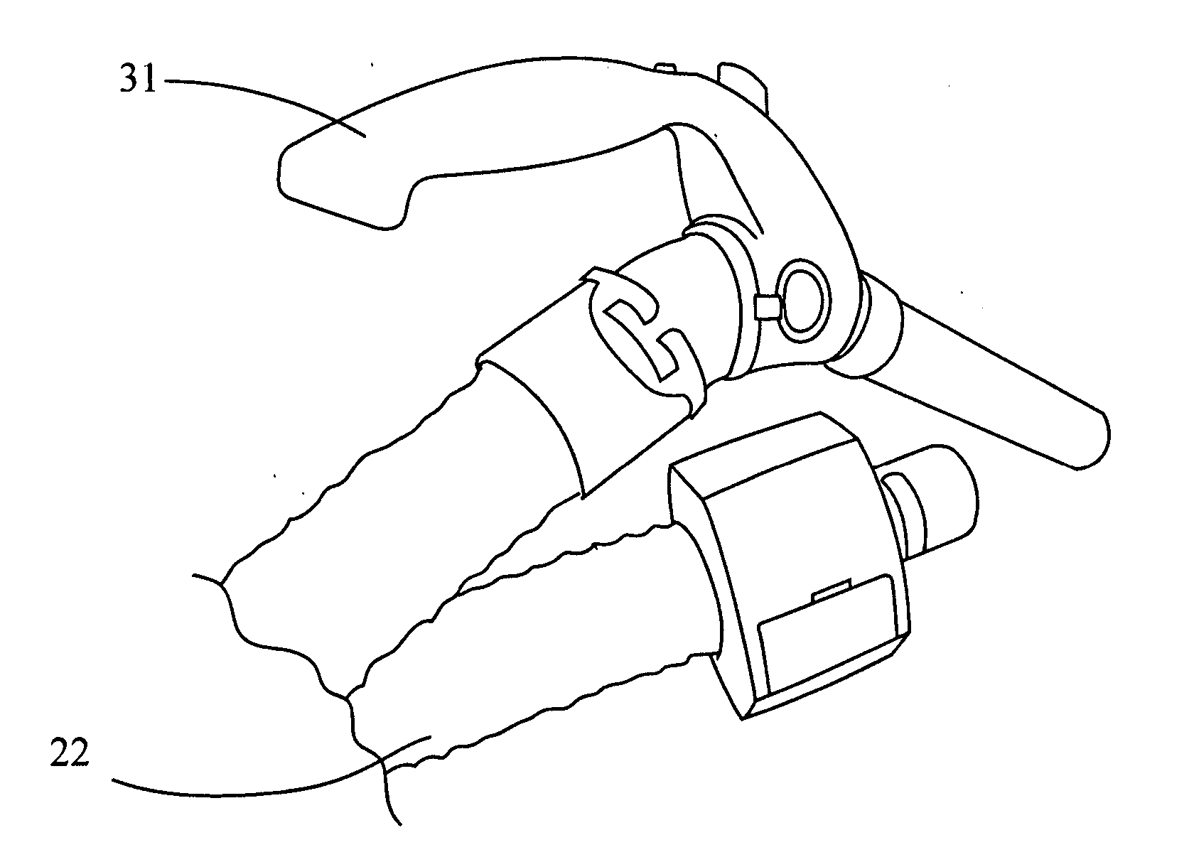
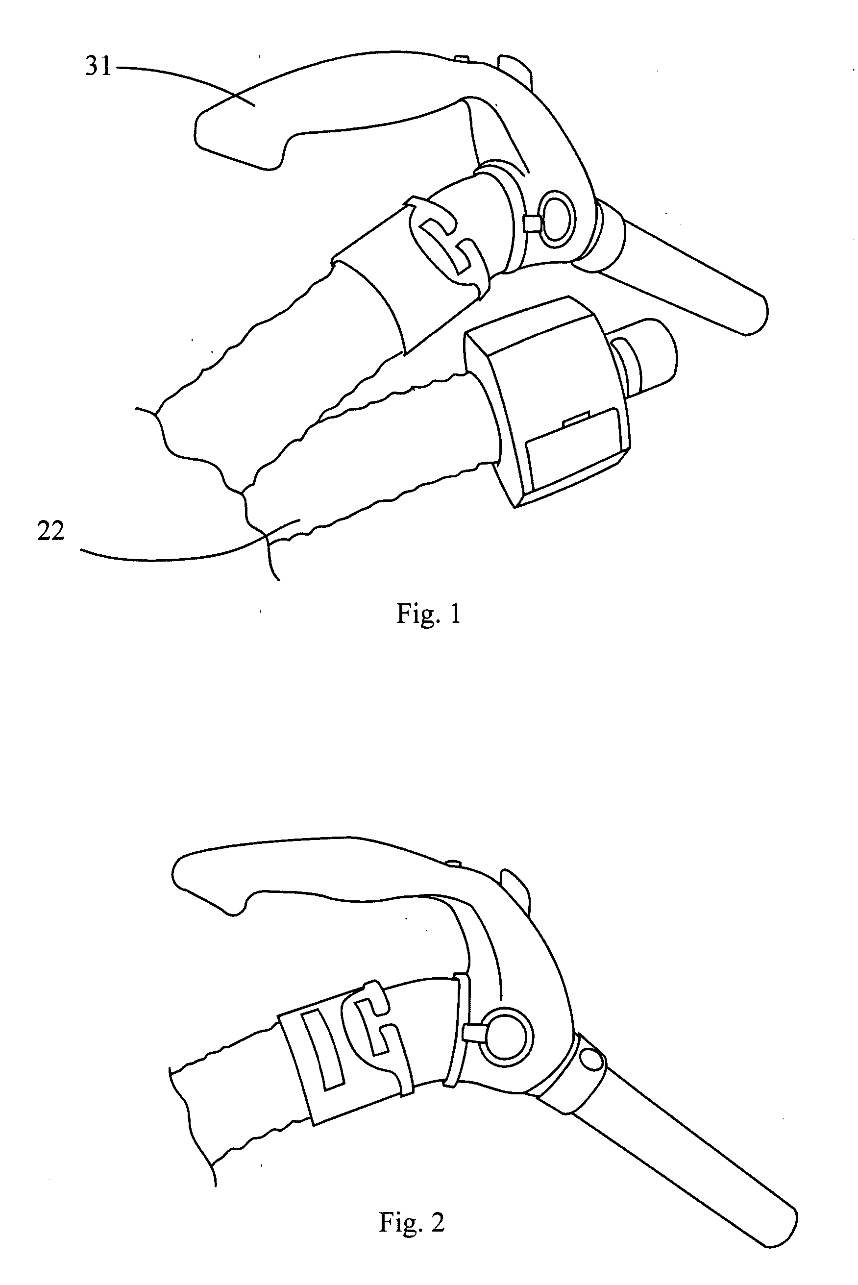
[0046] As seen in FIG. 1 there is one example of an embodiment of the central vacuum cleaner hose assembly 10, (hereinafter hose assembly) of the present invention. Although shown in connection with a receiver on an end fitting that is on one end of the hose, it will also be appreciated that the receiver can be elsewhere. For example, the receiver can be on the wall outlet or on the vacuum generating portion of the system of any other suitable location. The hose assembly of the present invention includes a first end fitting 20, a second end fitting 30, and a flexible hose 70. It will also be appreciated by those skilled in the art that the shape of the handle 20 and the end fitting 30 described in connection with one embodiment of the present invention can vary as desired. The hose may be any one of the hoses that are typically used in the art. As mentioned in the background of the invention, the switch in the handle may communicate with either the end fitting or the power head, for...


PUM


Abstract

The present invention includes a flexible hose with at least two end fitting. The first end fitting is inserted into the wall valve of the central vacuum cleaner system. The first end fitting is generally rectangular in shape and may have a kill switch located thereto. The first end fitting may be used as a receiver. In addition the first end fitting may include a generally cylindrical coupling member. The coupling member may include at least one contact member. The contact member may be located on the outer circumferential surface of the coupling member. The second end fitting may be shaped like a handle for controlling the power head. In addition the second end fitting may be used as the transmitter. Located on the second end fitting may be an indicator light that lets the user know if the handle is transmitting to the first end fitting.

Description

[0001] This application claims priority on U.S. Application Ser. No. 60 / 794,023 filed Apr. 21, 2006, the disclosures of which are incorporated herein by reference.FIELD OF INVENTION [0002] The present invention relates to improvements in vacuum systems. More specifically, the present invention relates to a vacuum handle having a radio frequency transmitter and an associated receiver for operating a vacuum system, in particular a vacuum system such as a central vacuum system. The vacuum handle communicates with the system through a receiver via a radio frequency remote control. The receiver may be an endfitting on the hose itself or on the system or elsewhere. BACKGROUND OF THE INVENTION [0003] A central vacuum power unit sits in an out-of the-way area such as your garage, basement, or utility room. Wall inlet valves are then installed in various locations throughout the home and connected to the power unit through tubing. Generally, the tubing can be run through the attic, basement ...

Claims


Application Information

Patent Timeline
Patent Type & Authority Applications(United States)
IPC IPC(8): A47L9/24
CPCA47L5/38A47L9/246A47L9/248A47L9/32A47L9/2884A47L9/2889A47L9/2894A47L9/2857
Inventor HERRON, ROY HOWARD JR.
Owner HERRON ROY HOWARD JR
Why Eureka
Try Eureka