
Distance measuring apparatus

a technology of distance measurement and measuring apparatus, which is applied in the direction of distance measurement, instruments, surveying and navigation, etc., can solve the problems of inability to obtain accurate peak values, inability to compensate, and inability to avoid the amplifying circuit from being supersaturated for great-reflected light intensity, etc., to achieve simple and cheap circuit configuration

Active Publication Date: 2008-03-20
HOKUYO AUTOMATIC CO
View PDF11 Cites 35 Cited by
  • Summary
  • Abstract
  • Description
  • Claims
  • Application Information

AI Technical Summary

Benefits of technology

[0013] In view of the above-mentioned problems, it is therefore an object of the present invention to provide a distance measuring apparatus that can carry out a distance compensation at a high precision under a stable operation in a cheap circuit, without any arrival at a supersaturate state for a great reflected light intensity, while increasing a gain of an amplifying circuit, in order to accurately detect even a weak reflected light.
[0017] So, a value determined by integrating the output by the integration processor becomes the total electric charge flowing through the photodiode by inputting the reflected light. Thus, the compensator can accurately compensate the delay time or the distance in accordance with the integration value. Hence, there is no necessity of installing the different amplifying circuit to determine the total electric charge flowing through the photodiode.
[0021] According to the foregoing configuration, the output of the AD converter to determine the integration value is doubly used to detect the detection timing of the reflected light. Thus, the simple cheap circuit configuration can be attained.

Problems solved by technology

Thus, this has a problem that, since a variation is generated in the rise edge of the reflected signal, this variation occurs as the error of the calculated distance.
As shown in FIG. 13B, when the intensity of the reflected light becomes great and the amplifying circuit is supersaturated, this has a problem that the accurate peak value cannot be obtained, thereby making the compensation impossible.
In order to enlarge the detection range of the measurement target object, if the gain of the amplifying circuit is increased so as to accurately detect even the weak reflected light, it is impossible to avoid the amplifying circuit from being supersaturated for the great-reflected light intensity.
However, the compensation technique described in Japanese Unexamined Patent Publication No.
H10-20035A has a problem where, although the distance compensation can be carried out correspondingly to a dynamic range where a reflected light intensity is wide, in order to measure the total charge amount, a different amplifying circuit is required, which results in an expensive part cost, and when the reflected light intensity is small, the linearity of the amplifying circuit is poor, which results in the drop in a compensation precision.
Moreover, when the amplifying circuit becomes supersaturated, a large amount of leakage currents flow into the amplifying circuit.
Thus, there is a problem that the distortion and crack of the waveform and the swinging to a minus direction are generated, thereby making the operation unstable.

Method used


Image

  • Distance measuring apparatus
  • Distance measuring apparatus
  • Distance measuring apparatus

Examples


Embodiment Construction

[0041] The embodiment of a scanning type distance measuring apparatus as one example of the distance measuring apparatus according to the present invention will be described below with reference to the drawings.

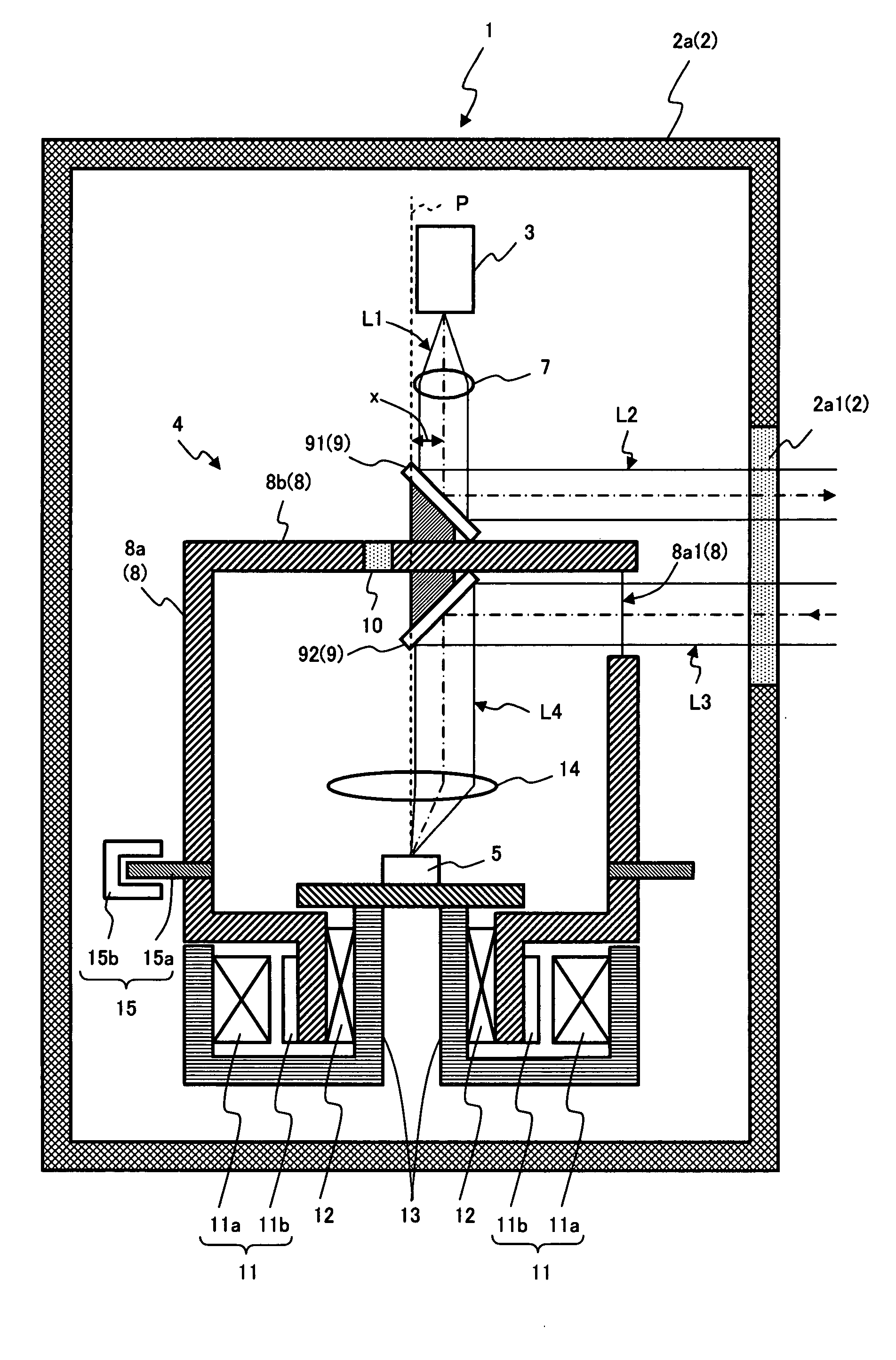
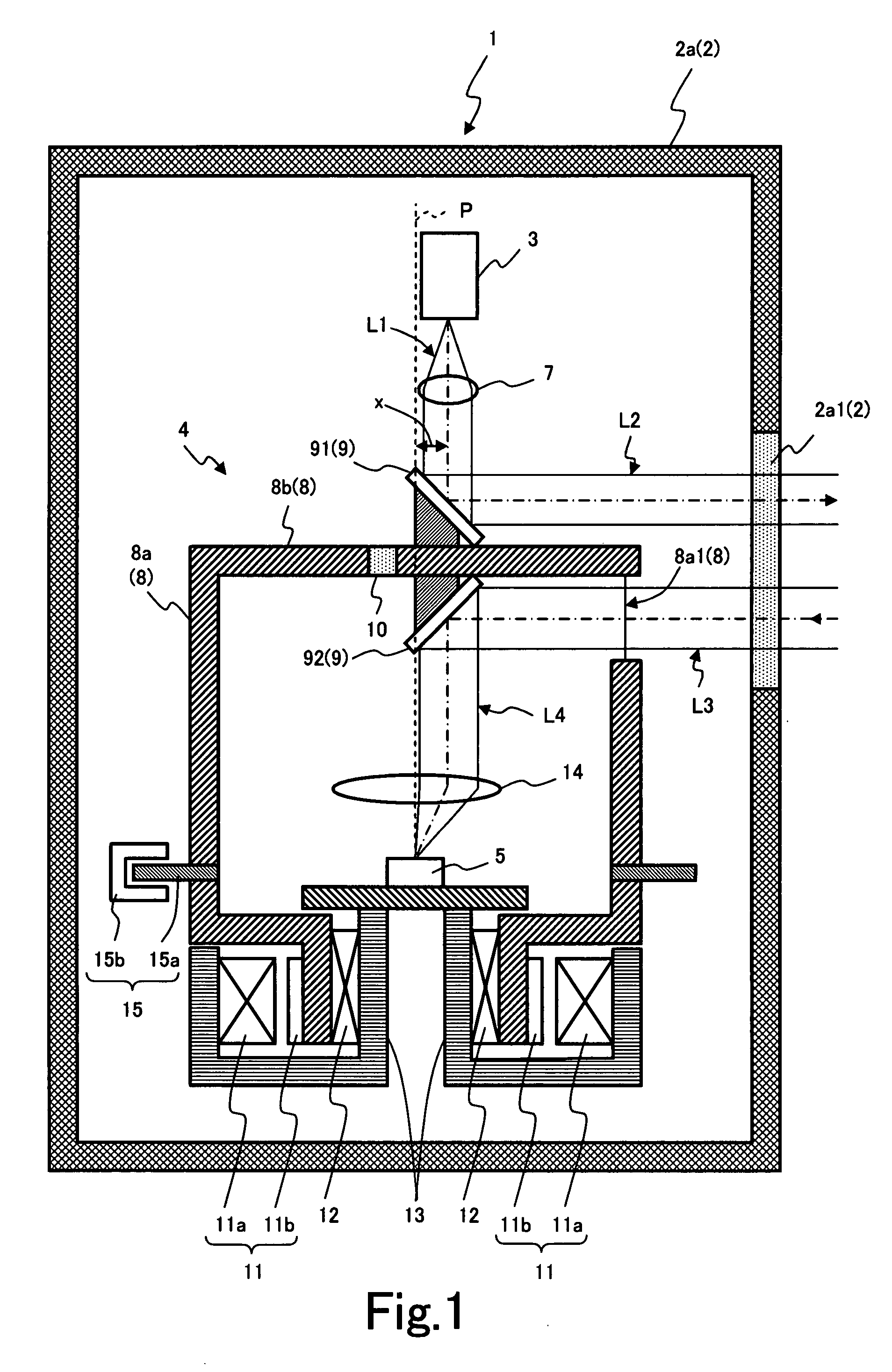
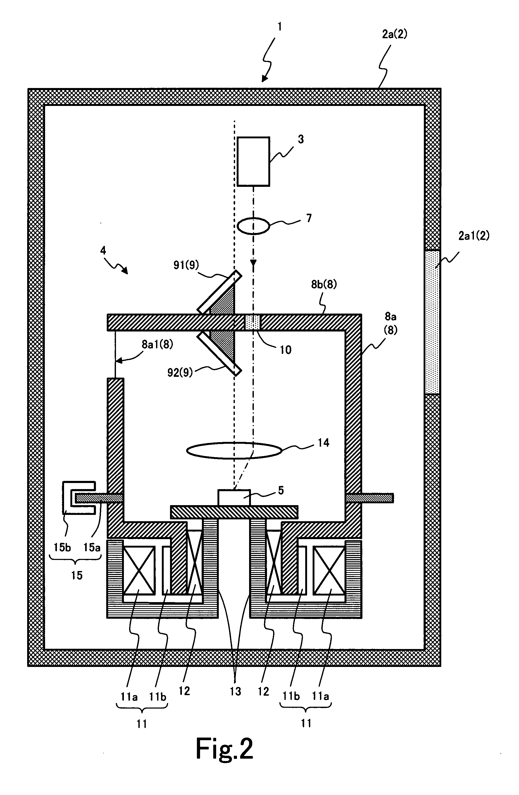
[0042]FIG. 1 is a schematic longitudinal sectional view showing the entire configuration of the scanning type distance measuring apparatus. As shown in FIG. 1, this scanning type distance measuring apparatus 1 contains a housing 2. Also, a light projector 3, a scanner 4 and a light receiver 5 are contained as the main members inside this housing 2.

[0043] The housing 2 is cylindrical where both ends of an up / down direction in FIG. 1 is closed, and a light transmitting window 2a1 having a constant width in the up / down direction is formed along the side wall (the right side wall shown in FIG. 1) where a part is removed from the entire circumference of a circumference wall 2a. The measurement light outputted by the light projector 3, which will be described later, and the refle...


PUM


Abstract

There is provided a distance measuring apparatus, which can attain a distance compensation of a high precision and can be stably operated by using a cheap circuit, without any arrival at a supersaturated state for a great reflected light intensity, while a gain of an amplifying circuit is made higher, in order to accurately detect even a weak reflected light. The apparatus comprises: a light source for outputting a pulsed measurement light towards a measurement target object; a light receiver for detecting the reflected light from the measurement target object; and a calculator for calculating the distance from the measurement target object on the basis of the delay time between the output timing of the measurement light and the detected timing of the reflected light by the light receiver, and a light receiver 5 is composed of a photodiode PD for photo-electrically converting the reflected light, a diode D that is connected in series to the photodiode PD and clamps the light current generated in the photodiode PD, and an amplifying circuit 50 for amplifying the output of the photodiode PD, and it contains an integration processor for integrating the output of the amplifying circuit 50 and a distance compensator for compensating the distance in accordance with the output of the integration processor.

Description

BACKGROUND OF THE INVENTION [0001] 1. Field of the Invention [0002] The present invention relates to a distance measuring apparatus based on a TOF (Time of Flight) method, which drives a light source, such as a semiconductor laser, a light emission diode or the like, and emits a pulse-shaped measurement light to a measurement target object and then detects a reflected light from the measurement target object and in accordance with a flight time (delay time) of the light between an output timing of the measurement light and a detection timing of the reflected light, and consequently measures the distance between the light source and the measurement target object. [0003] 2. Description of the Related Art [0004] This type of distance measuring apparatus is used in a visual sensor of a robot or an automatic guided vehicle, or an opening / closing sensor of a door or a monitor sensor for detecting a presence or absence of a raider to a monitor region, or a safety sensor for detecting a per...

Claims


Application Information

Patent Timeline
Patent Type & Authority Applications(United States)
IPC IPC(8): G01C3/08G01S17/10G01S7/4865
CPCG01S17/10G01S7/4873G01S7/4865
Inventor MORI, TOSHIHIROHINO, MASANORI
Owner HOKUYO AUTOMATIC CO
Learn More