Method and Apparatus for Detecting Pressure Distribution in Fluids

a technology of fluids and pressure distribution, applied in the direction of fluid pressure measurement, optical radiation measurement, instruments, etc., can solve the problems of difficult to detect the pressure distribution of fluids, the inability to use side-hole fibres incorporating either fbgs or rocking filters, and the inability to measure the pressure distribution. , to achieve the effect of easy measurement and simple deployment and maintenance of waveguides

Active Publication Date: 2008-03-20
VIAVI SOLUTIONS INC
View PDF12 Cites 13 Cited by
  • Summary
  • Abstract
  • Description
  • Claims
  • Application Information

AI Technical Summary

Benefits of technology

[0070] So, by looking at the distribution of external isotropic pressure along (e.g. the length or the whole length of) the optical waveguide over time, the propagation of a tsunami can be detected. These aspects of the invention are particularly effective, as the waveguide can extend over several tens of kilometres. Not only does this allow remote detection of the tsunami, it can help to provide effective early warning, well before a tsunami reaches a coast. Furthermore, changes in the distribution of pressure exerted along the waveguide by a tsunami can provide useful scientific data about the nature of tsunamis, not always possible with other systems that have shorter reach and/or restricted pressure measurement locations.
[0071] In this regard, the waveguide may of course be located at any appropriate position along the expected path of a tsunami, e.g. close to a geographical fault line or such like. However, it is pr

Problems solved by technology

In addition, the silica from which optical fibres are usually made is relatively incompressible.
This insensitivity makes them fairly impractical for pressure measurement.
However, the use of side-hole fibres incorporating either FBGs or rocking filters has a number of problems.
This means that the measurement is restricted by the size and location of the FBG or rocking filter along the length of the fibre.
This significantly limits the usefulness of optical fibres for pressure measurement.
Furthermore, it is very difficult to measure the pressure applied to a fibre at multiple positions along its length using FBGs, as the provision and use of multiple FBGs in a single optical fibre is limited and complex.
As it is only possible to interrogate the fibre with light having a limited wavelength range, say around 60 nm, the number of different FBGs that can be used in a single fibre is severely limited, say to around 30.
However, it is impossible to avoid totally influence

Method used


Image

  • Method and Apparatus for Detecting Pressure Distribution in Fluids
  • Method and Apparatus for Detecting Pressure Distribution in Fluids
  • Method and Apparatus for Detecting Pressure Distribution in Fluids

Examples


Embodiment Construction

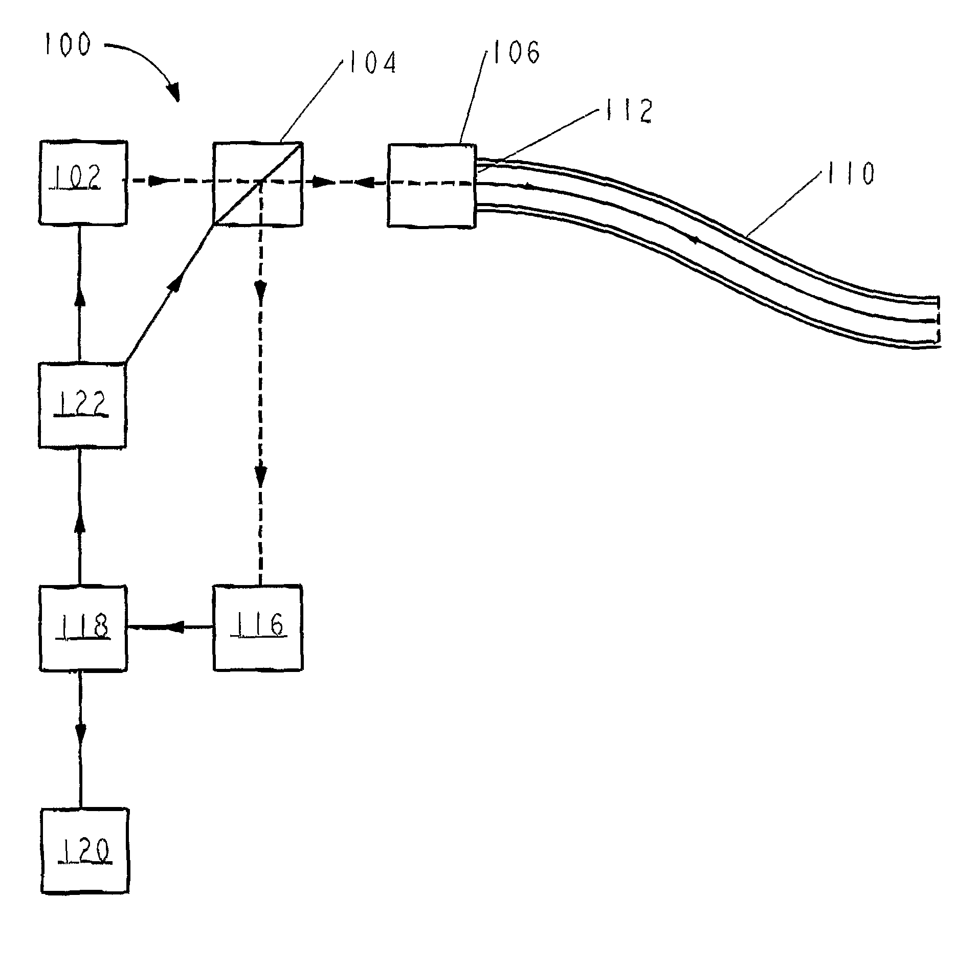
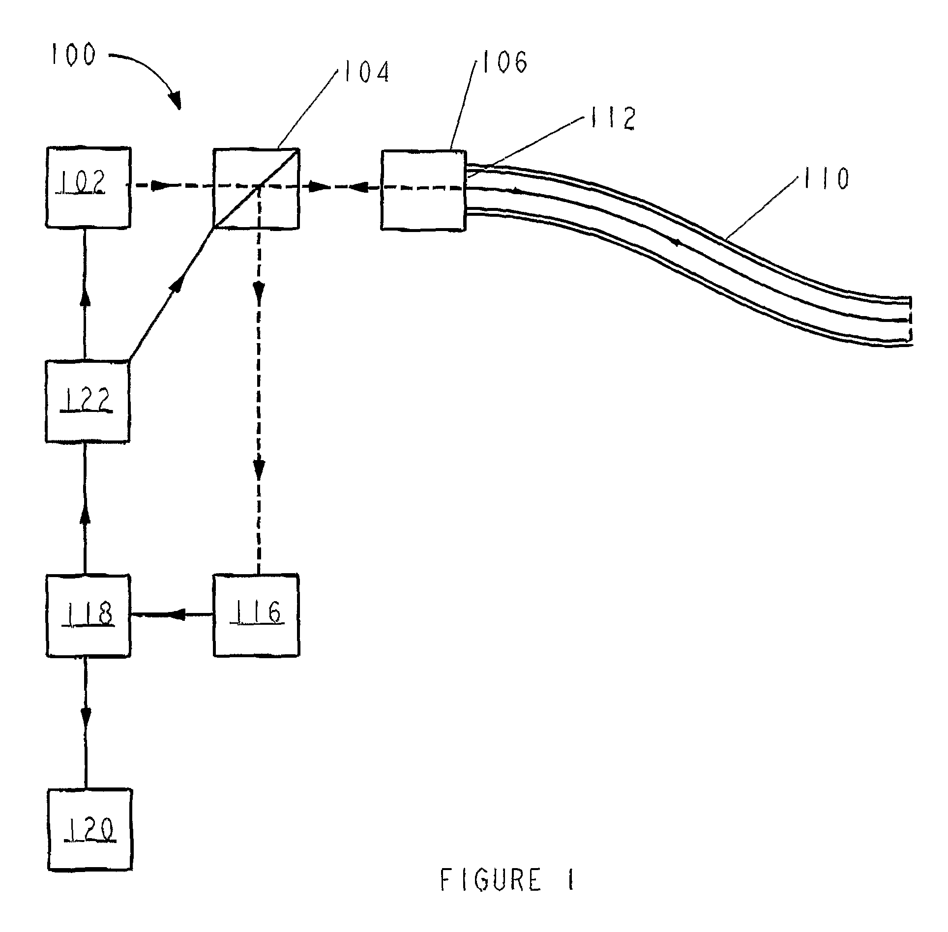
[0089] Referring to FIG. 1, a pressure sensing apparatus 100 comprises a light source 102 which, in this embodiment, is a tunable laser able to transmit coherent light across a range of wavelengths between around 1550 nm and 1560 nm. (In other embodiments, any range of wavelengths between about 1300 nm and 1600 nm could be used.) Light transmitted by the light source 102 is directed into a polarisation processing unit (PPU) 104. The PPU 104 is operable to condition the polarisation state of the light received from the light source 102 and to transmit some of the light incident on it from the light source 102 to an optical coupler 106.

[0090] The optical coupler 106 is attached to an end 112 of an optical fibre 110 and directs light from the PPU 104 into the optical fibre 110 through the end 112 of the optical fibre 110 to which it is attached. The optical coupler 106 also transmits light emitted from the end 112 of the optical fibre 110, for example by backscattering in the optical ...


PUM


Abstract

A pressure sensing apparatus has a light source for transmitting pulses of light along a monomode optical fibre. The polarisation of light backscattered from the light pulses in the optical fibre is detected by a polarisation processing unit (PPU) and a photo detector. The optical fibre is adapted to deform asymmetrically under the influence of applied external isotropic pressure, e.g. from a fluid. The deformation causes the birefringence of the optical fibre to change proportionally to the applied pressure. The change in birefringence can be determined from the detected polarisation of the backscattered light, allowing detection of pressure distribution in the fluid. Importantly, the construction of the optical fibre is such that the birefringence beat length of the optical fibre at the wavelength of light propagated by the fibre remains more than twice the spatial length of the light pulses transmitted along the optical fibre. Applications of the invention include detection of fluid flow; location of an interface between two fluids of different density; and tsunami detection.

Description

FIELD OF THE INVENTION [0001] This invention relates to a method and apparatus for detecting pressure distribution in fluids, particularly, but not exclusively, by analysing a single mode side-hole optical fibre using polarisation optical time domain relfectometry. The invention also includes methods and apparatus for measuring fluid flow; determining the location of an interface between two fluids of different densities; and detecting tsunamis. BACKGROUND TO THE INVENTION [0002] When external pressure is applied to an optical fibre, the core of the fibre experiences strain which varies with the applied pressure. Due to a phenomenon known as the “elasto-optic effect”, the way in which light propagates in the fibre's core changes as the strain experienced by the core changes. So, by looking at the way in which the light propagation properties of the fibre's core change, changes in strain and hence pressure applied to the fibre can measured. [0003] Most conventional optical fibres hav...

Claims


Application Information

Patent Timeline
IPC IPC(8): G01L7/00G01B11/00G01L1/00G01L11/02G01P5/14
CPCG01L11/025G01D5/268G01P5/14
Inventor ROGERS, ALAN JOHNKANELLOPOULOS, SOTIRIS EMILSHATALIN, SERGEY VLADIMIR
Owner VIAVI SOLUTIONS INC
Why Eureka
Try Eureka