
Optical pickup device

Inactive Publication Date: 2008-03-20
FUNAI ELECTRIC CO LTD
View PDF10 Cites 5 Cited by
  • Summary
  • Abstract
  • Description
  • Claims
  • Application Information

AI Technical Summary

Benefits of technology

[0010] The present invention provides an optical pickup device including: first and second objective lenses having different optical characteristics; a lens holder provided with first and second lens receiving cylindrical parts to which the first and second objective lenses are attached, respectively, so that distance from the first objective lens to the optical recording medium becomes shorter than distance from the second objective lens to the optical recording medium without overlapping the objective lenses; and a buffer member formed in a cylindrical shape so as to surround the periphery of the first objective lens, and having a projection for preventing collision between the first objective lens and the optical recording medium, the projection being provided at an end on the optical recording medium side. The second objective lens is fixed in the second lens receiving cylindrical part, and a lens tilt adjusting and holding structure for holding the first objective lens so that tilt of the first objective lens can be adjusted is added to the buffer member and the first lens receiving cylindrical part.
[0011] With the configuration, after a tilt adjustment of the second objective lens with respect to an optical recording medium, a tilt of the first objective lens with respect to an optical recording medium, the lens holder, and the second objective lens can be adjusted by the lens tilt adjusting and holding structure. Consequently, coma aberration which occurs due to a relative tilt error between the objective lenses when the components of the optical pickup device are actually combined can be properly suppressed by the tilt adjustment. After attachment of the objective lenses to the lens receiving cylindrical parts of the lens holder, the coma aberration can be corrected by adjusting the tilt of each of the objective lenses. Consequently, it becomes unnecessary to strictly manage the dimensional precision of the objective lenses and the lens receiving cylindrical parts so that the objective lenses can be attached to the lens receiving cylindrical parts always in a predetermined state, manufacture of the parts becomes easier, and productivity can be improved. Since the lens tilt adjusting and holding structure is added to the buffer member and the first lens receiving cylindrical part of the lens holder, it is unnecessary to separately manufacture and employ a member dedicated to adjust the tilt of the first objective lens with respect to the lens holder and the second objective lens. Thus, increase in the manufacture cost can be suppressed. Further, the coma aberration which occurs in the second objective lens is corrected by adjusting the tilt of the second objective lens together with the lens holder and, after that, the coma aberration which occurs in the first objective lens is corrected by adjusting the tilt of the first objective lens by the lens tilt adjusting and holding structure. Therefore, even when the laser beam is condensed by any of the objective lenses and emitted to the optical recording medium, coma aberration which occurs in a light spot formed on the optical recording medium can be properly suppressed, and the reproducing performance or recording performance of the optical pickup device can be improved.

Problems solved by technology

If the working distance becomes short to a certain extent, in the case such that focus servo is deviated, an objective lens and an optical recording medium collide with each other and are damaged.
In a light spot formed by condensing a laser beam by an objective lens onto an optical recording medium, coma aberration occurs due to a manufacture error in the objective lens or an error of attachment to a lens holder.
When coma aberration becomes large to a certain degree, the reproduction performance and the recording performance deteriorate.
However, in the case of fixing a plurality of kinds of objective lenses in a single lens holder, the objective lenses are not always fixed by the lens holder so that the tilting directions of the objective lenses capable of eliminating coma aberration which occurs in the objective lenses become the same.
Consequently, even when the objective lenses in the lens holder are tilted in the same direction to correct coma aberration which occurs in one of the objective lenses, there is the possibility that coma aberration which occurs in the other objective lens becomes very large.
Therefore, the techniques cannot properly correct coma aberration caused by a relative tilt error between the objective lenses when components of the optical pickup device are actually combined.

Method used


Image

  • Optical pickup device
  • Optical pickup device
  • Optical pickup device

Examples


Embodiment Construction

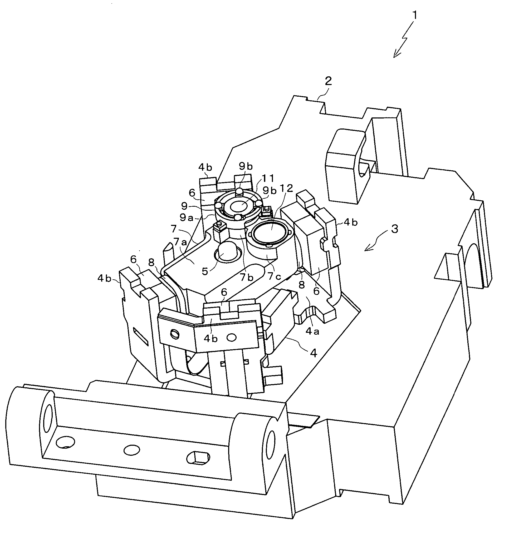
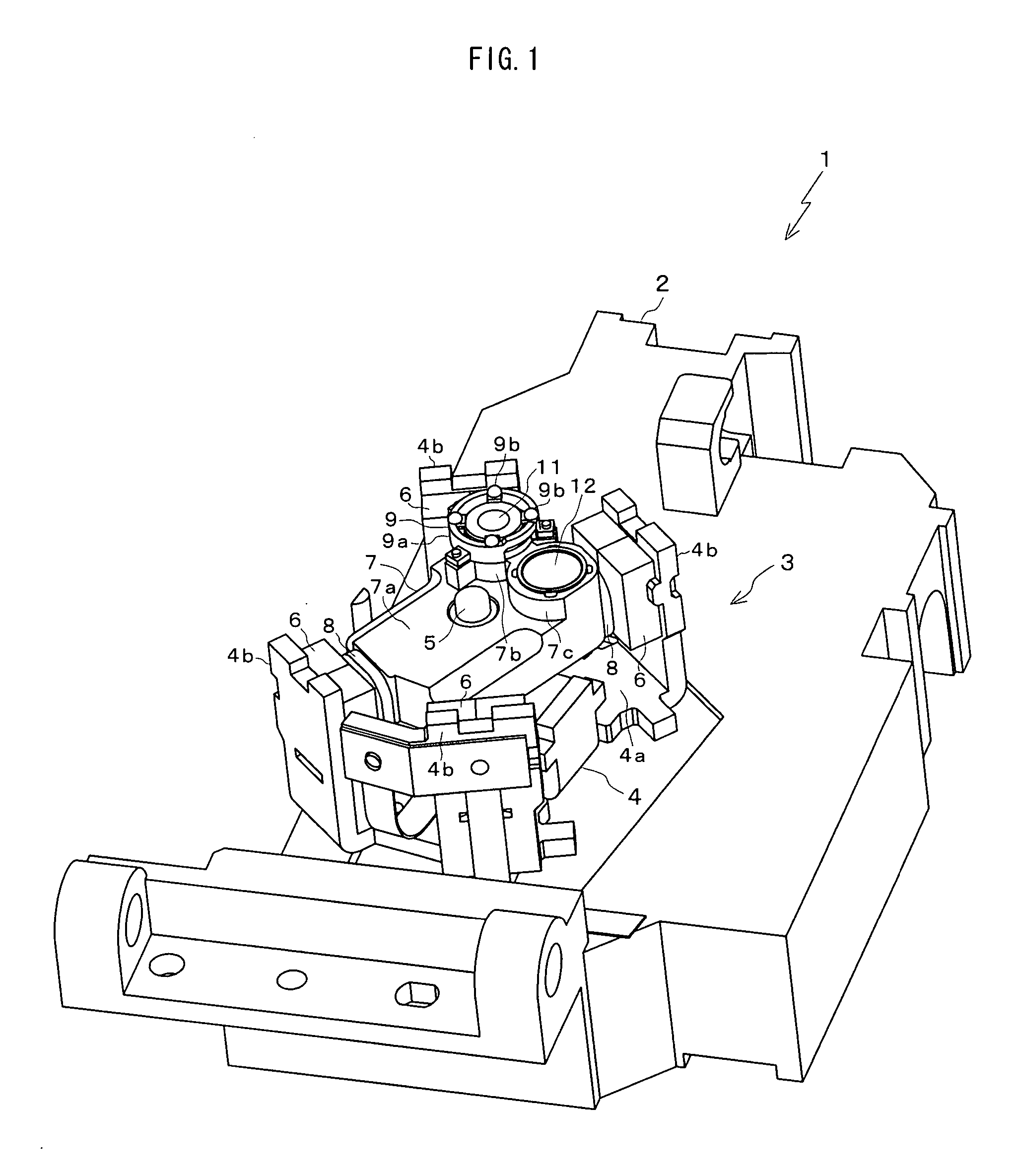
[0030]FIG. 1 is a perspective view generally showing an optical pickup device 1 according to an embodiment of the present invention. The optical pickup device 1 is mounted on a multi-type disc player, disc recorder, or the like for reproducing / recording information from / to a DVD (Digital Versatile Disc) and a Blu-ray Disc as an example of an optical recording medium.

[0031] A base 2 of the optical pickup device 1 is a fixed member which is fixed to a chassis of a disc player or the like. To the base 2, parts such as various optical systems and drive systems are attached. In FIG. 1, only an actuator 3 attached on the base 2 is shown. A shaft 5 is fixed so as to penetrate the center of a body 4a of a base 4 of the actuator 3. The base 4 and the shaft 5 are attached with a predetermined tilt to the top face of the base 2. The base 4 has four side parts 4b bent upright from the body 4a. The body 4a is perpendicular to the shaft 5, and the side parts 4b are parallel with the shaft 5. Mag...


PUM


Abstract

The present invention provides an optical pickup device capable of properly suppressing coma aberration which occurs due to a relative tilt error between objective lenses. The optical pickup device includes: first and second objective lenses having different optical characteristics; a lens holder provided with first and second lens receiving cylindrical parts to which the first and second objective lenses are attached so that distance from the first objective lens to an optical recording medium becomes shorter than distance from the second objective lens to the optical recording medium without overlapping the objective lenses; and a buffer member formed in a cylindrical shape so as to surround the periphery of the first objective lens, and having a projection for preventing collision between the first objective lens and the optical recording medium, the projection being provided at an end on the optical recording medium side. In the optical pickup device, the second objective lens is fixed in the lens receiving cylindrical part, and a lens tilt adjusting and holding structure for holding the first objective lens so that tilt of the first objective lens can be adjusted is added to the buffer member and the first lens receiving cylindrical part.

Description

BACKGROUND OF THE INVENTION [0001] 1. Field of the Invention [0002] The present invention relates to an optical pickup device including a plurality of objective lenses having different optical characteristics. [0003] 2. Description of the Background Art [0004] Some optical pickup devices include a plurality of kinds of objective lenses having optical characteristics corresponding to different kinds of optical recording medium such as a DVD (Digital Versatile Disc) and a Blu-ray Disc (trademark) in order to reproduce / record information from / to the optical recording medium. In such an optical pickup device, a plurality of kinds of objective lenses are attached to a single lens holder and used while being switched in accordance with the kind of an optical recording medium. Specifically, for example, at the time of reproducing information from a DVD, a laser beam emitted from a light source is condensed by an objective lens adapted to a DVD and the condensed light is emitted to the DVD....

Claims


Application Information

Patent Timeline
IPC IPC(8): G11B7/00G02B7/02
CPCG02B7/003G02B27/0025G02B27/62G11B2007/0006G11B7/1201G11B7/22G11B7/082G11B7/121
Inventor HOSODA, RYOZOTAKAHASHI, KAZUHIROHATANO, SHINYASASAOKA, HIROMASA
Owner FUNAI ELECTRIC CO LTD
Features
  • Generate Ideas
  • Intellectual Property
  • Life Sciences
  • Materials
  • Tech Scout
  • Unparalleled Data Quality
  • Higher Quality Content
  • 60% Fewer Hallucinations
Learn More