Driver laser for extreme ultra violet light source device

a technology of ultra violet light source and driver laser, which is applied in the direction of laser optical devices, laser details, electrical equipment, etc., can solve the problems of reducing reducing the efficiency of laser beam amplitude, and increasing the size of the driver laser

Inactive Publication Date: 2008-03-20
KOMATSU LTD +1
View PDF5 Cites 33 Cited by
  • Summary
  • Abstract
  • Description
  • Claims
  • Application Information

AI Technical Summary

Benefits of technology

[0023] According to the present invention, since self-oscillation light is suppressed, a

Problems solved by technology

Here, when Ep is larger, damage provided to optical elements, through which laser beam passes, becomes larger, and the optical elements deteriorate faster.
Arranging a plurality of amplifiers for multistage amplification in this manner causes a driver laser to be larger in size and more complicated, resulting in deterioration of reliability thereof.
In this case, however, efficiency is not good, because mos

Method used


Image

  • Driver laser for extreme ultra violet light source device
  • Driver laser for extreme ultra violet light source device
  • Driver laser for extreme ultra violet light source device

Examples


second embodiment

[0115] Next, a driver laser will be described.

[0116]FIG. 14 is a schematic diagram showing a principle of a driver laser according to the second embodiment. As shown in FIG. 14, the driver laser includes an oscillator 41 and an amplifier 43 for amplifying a laser beam emitted from the oscillator 41. The amplifier 43 has a polarizer 51, a discharge unit 52, a circular polarization mirror (λ / 4 phase retarding mirror) 56, a self-oscillation light filter 53, and a feedback mirror 55.

[0117] A laser beam (here, P-polarized) emitted from the oscillator 41 passes through the polarizer 51 and is transmitted through a first window to be input into the discharge unit 52. The laser beam (P-polarized) input into the discharge unit 52 from the polarizer 51 is amplified during passing through an excited laser medium.

[0118] The circular polarization mirror 56 converts the laser beam with linear polarization (P-polarization) amplified in the discharge unit 52 into a laser beam with circular polar...

third embodiment

[0137] Next, a driver laser according to the present invention will be described.

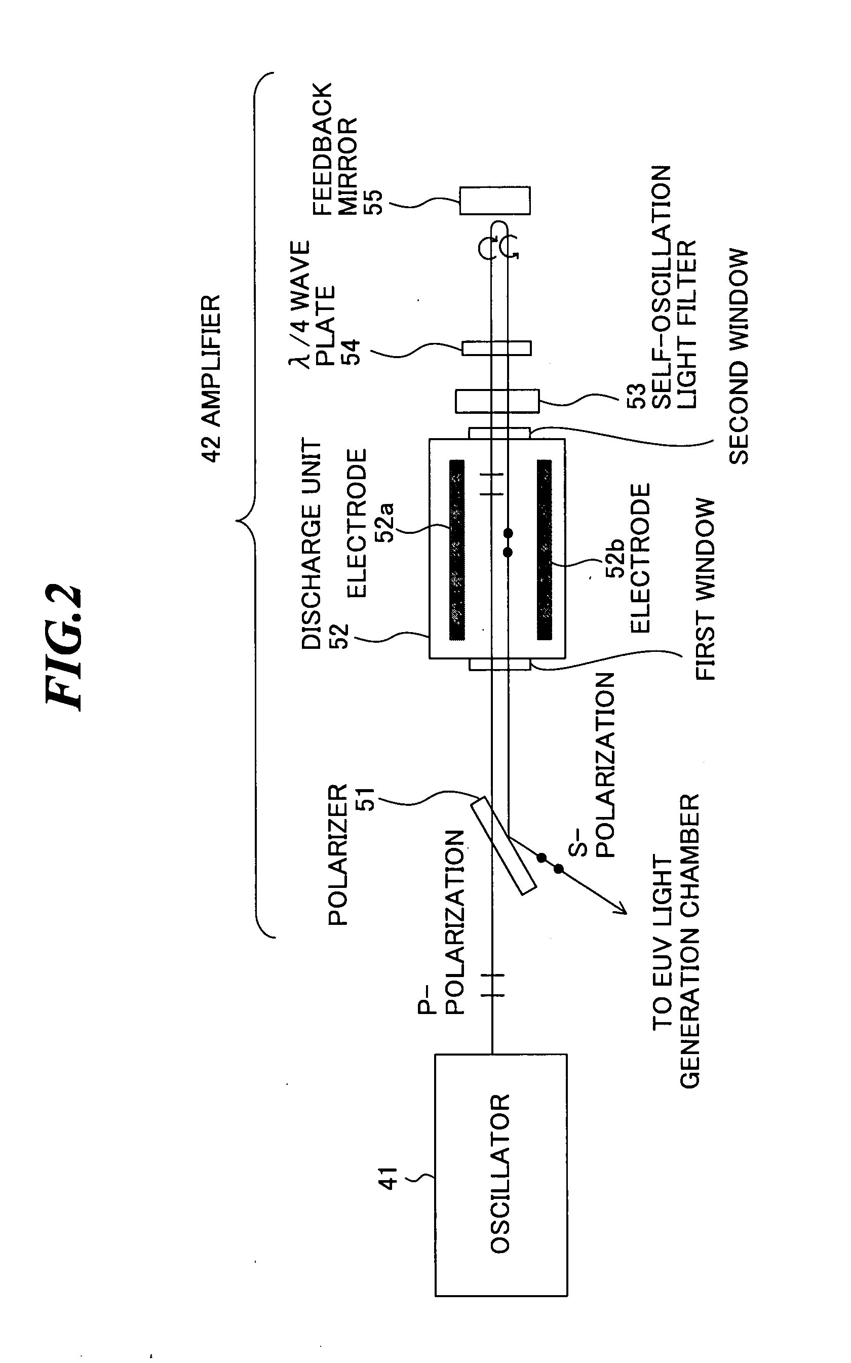
[0138]FIG. 18 is a schematic diagram showing a principle of a driver laser according to the third embodiment. As shown in FIG. 18, the driver laser includes an oscillator 41 and an amplifier 42.

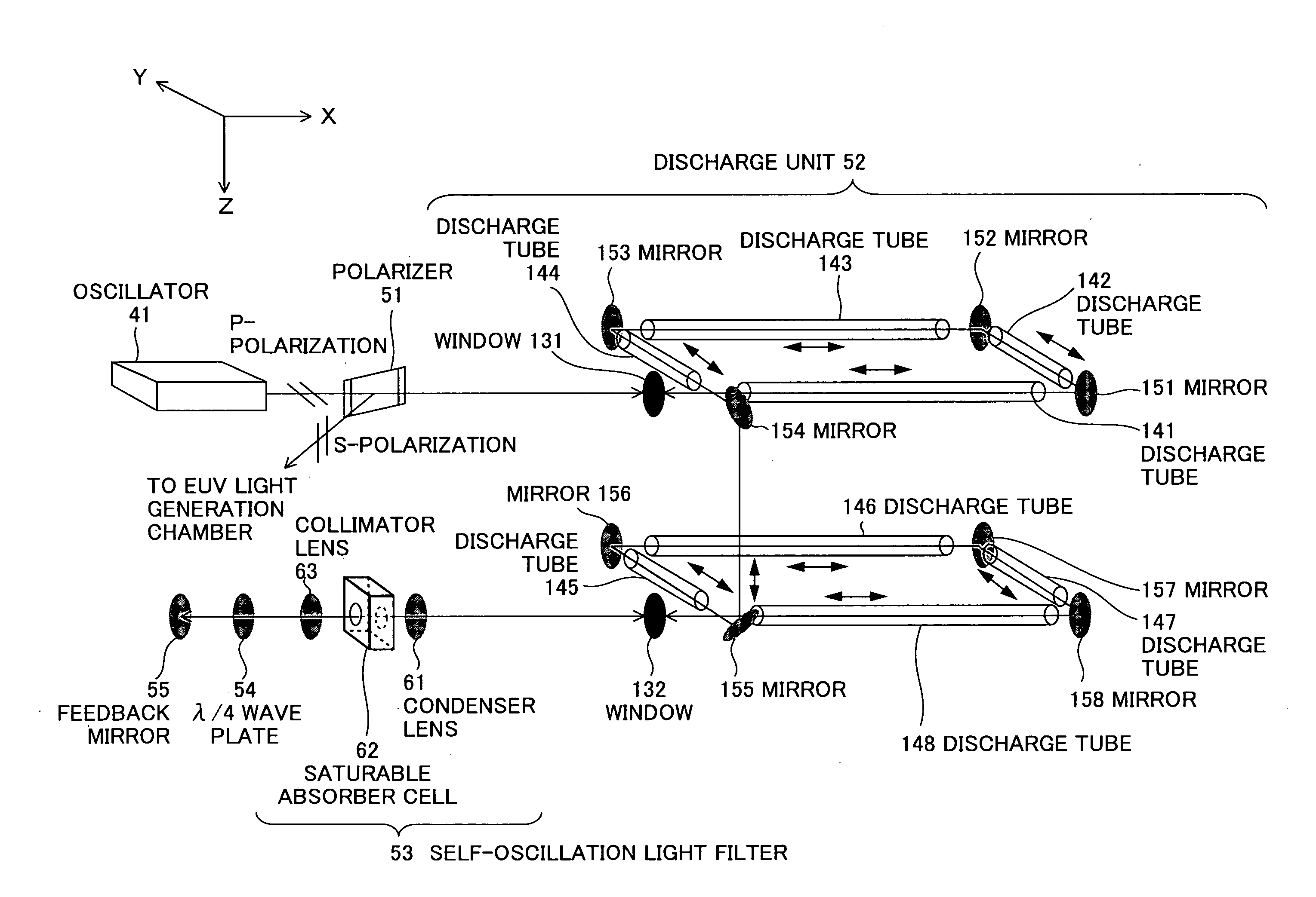
[0139] The oscillator 41 emits a laser beam (here, S-polarized) to a reflection surface with a coating of the polarizer 51 (surface on the side of the discharge unit 52). The laser beam (S-polarized) emitted from the oscillator 41 is reflected by the polarizer 51 to the right direction in the drawing and transmitted through a first window to be input into the discharge unit 52. The laser beam (S-polarized) input into the discharge unit 52 is amplified during passing through an excited laser medium.

[0140] The laser beam (S-polarized) amplified in the discharge unit 52 passes through a self-oscillation light filter 53. When a self oscillation has occurred in the discharge unit 52 and self-oscillation light has be...

fourth embodiment

[0147] Next, a driver laser according to the present invention will be described.

[0148]FIG. 19 is a schematic diagram showing a principle of a driver laser according to the fourth embodiment. As shown in FIG. 19, the driver laser includes an oscillator 41 and an amplifier 43.

[0149] The oscillator 41 emits a laser beam (here, S-polarized) to a reflection surface with a coating of a polarizer 51 (surface on the side of a discharge unit 52). The laser beam (S-polarized) emitted from the oscillator 41 is reflected by the polarizer 51 to the right direction in the drawing and is transmitted through a first window to be input into the discharge unit 52. The laser beam (S-polarized) input into the discharge unit 52 is amplified during passing through an excited laser medium.

[0150] The laser beam (S-polarized) amplified in the discharge unit 52 is reflected by a circular polarization mirror 56 to the upward direction in the drawing. The circular polarization mirror 56 converts the laser b...


PUM


Abstract

A driver laser for an extreme ultra violet light source device capable of suppressing self-oscillation light, amplifying a laser beam efficiently, and reducing a device size. The driver laser has an oscillator for generating a laser beam to output the generated laser beam, and at least one amplifier for amplifying the laser beam output from the oscillator to output the amplified laser beam. The amplifier includes a discharge unit which amplifies the laser beam by using energy of a laser medium excited by discharge, a feedback mirror which leads the laser beam output from the discharge unit to the discharge unit, a polarizer which leads the laser beam output from the oscillator into the discharge unit and also reflects the laser beam output from the discharge unit to a predetermined direction, and a self-oscillation light filter which attenuates self-oscillation light output from the discharge unit.

Description

BACKGROUND OF THE INVENTION [0001] 1. Field of the Invention [0002] The present invention relates to a driver laser for irradiating a target with light in an LPP (laser produced plasma) type EUV (extreme ultra violet) light source device that generates extreme ultra violet light to be used for exposing a semiconductor wafer or the like. [0003] 2. Description of a Related Art [0004] Recently, as semiconductor processes become finer, photolithography has been making a rapid progress to realize a higher resolution, and for the next generation, micro-fabrication of 100 nm to 70 nm, and further, micro-fabrication of 50 nm or less is being required. Accordingly, in order to meet the requirement of micro-fabrication of 50 nm or less, for example, exposure equipment is expected to be developed by combining an EUV light source generating extreme ultra violet light with a wavelength of approximately 13 nm and reduced projection reflective optics. [0005] In such an EUV light source device, gen...

Claims


Application Information

Patent Timeline
IPC IPC(8): H01S3/108
CPCH01S3/2232H01S3/2308H01S2301/02H01S3/005H01S3/2366
Inventor ARIGA, TATSUYAHOSHINO, HIDEOMIURA, TAISUKEENDO, AKIRA
Owner KOMATSU LTD
Why Eureka
Try Eureka