
Stimulation and recovery of heavy hydrocarbon fluids

a hydrocarbon fluid and hydrocarbon technology, applied in fluid removal, earth-moving drilling, borehole/well accessories, etc., can solve the problems of reducing the viscosity of hydrocarbon-containing materials, particularly heavy oil, bitumen and kerogen. the effect of viscosity reduction

Inactive Publication Date: 2008-03-27
HW PROCESS TECH
View PDF99 Cites 141 Cited by
  • Summary
  • Abstract
  • Description
  • Claims
  • Application Information

AI Technical Summary

Benefits of technology

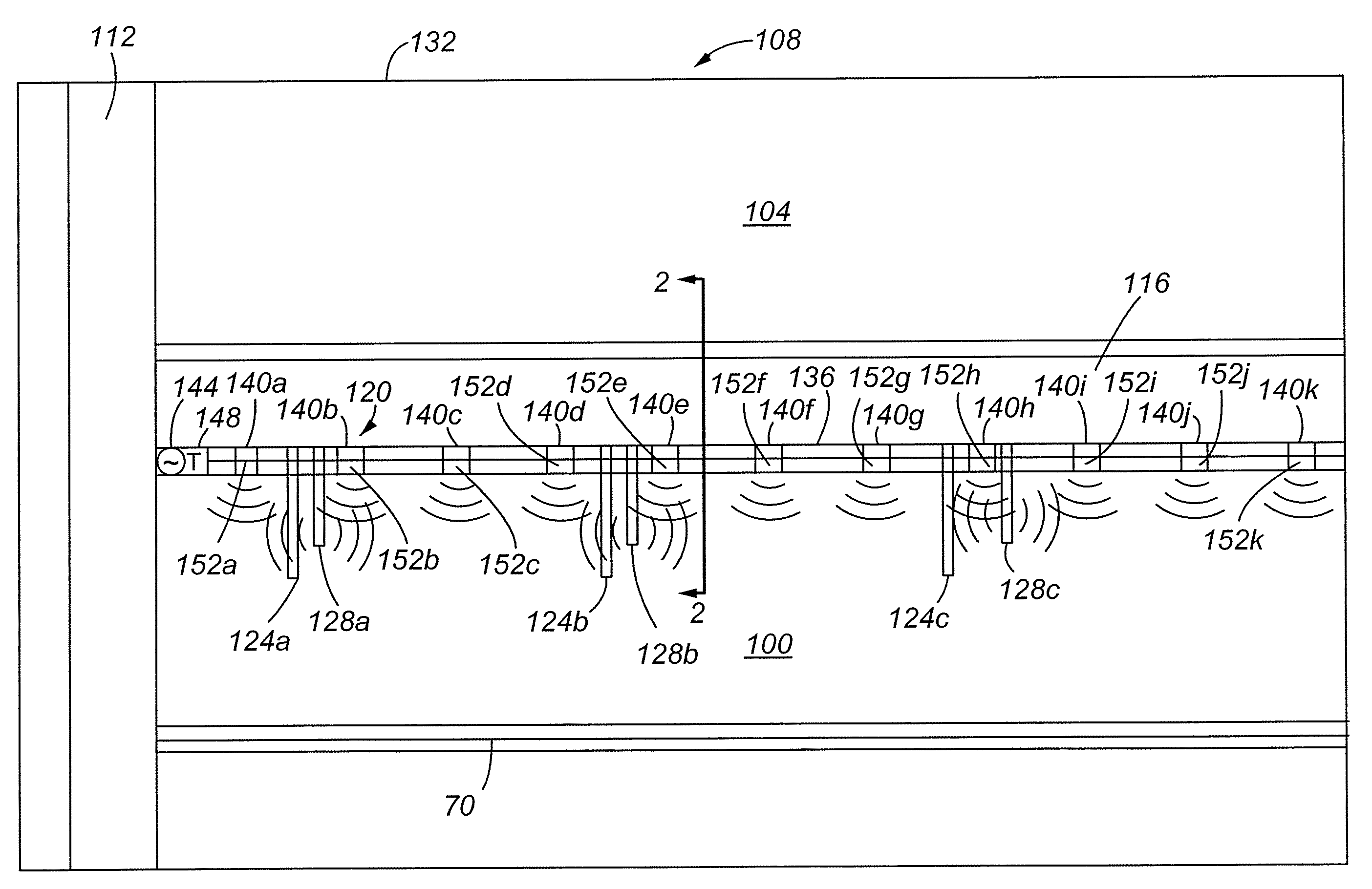
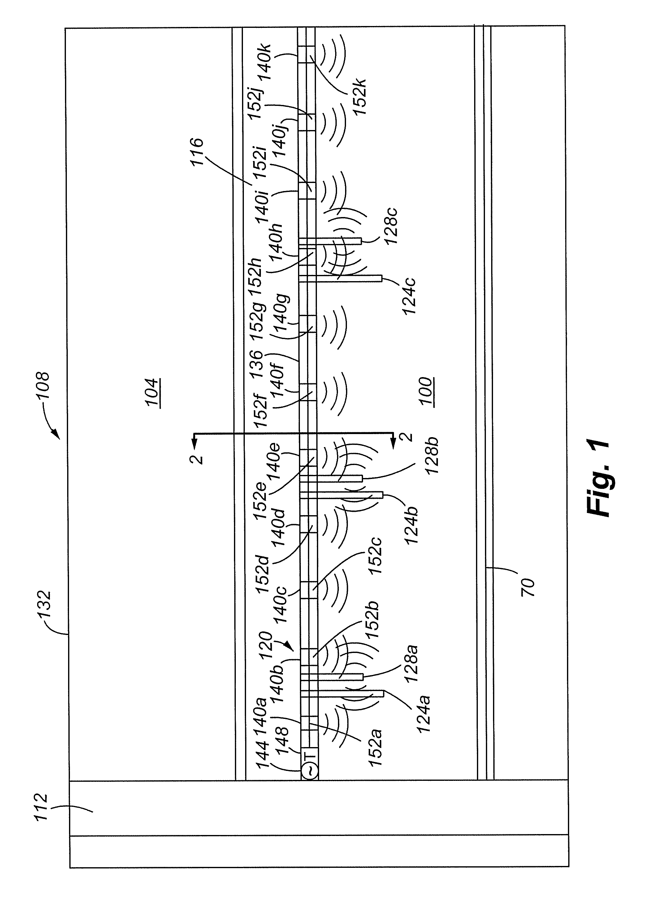
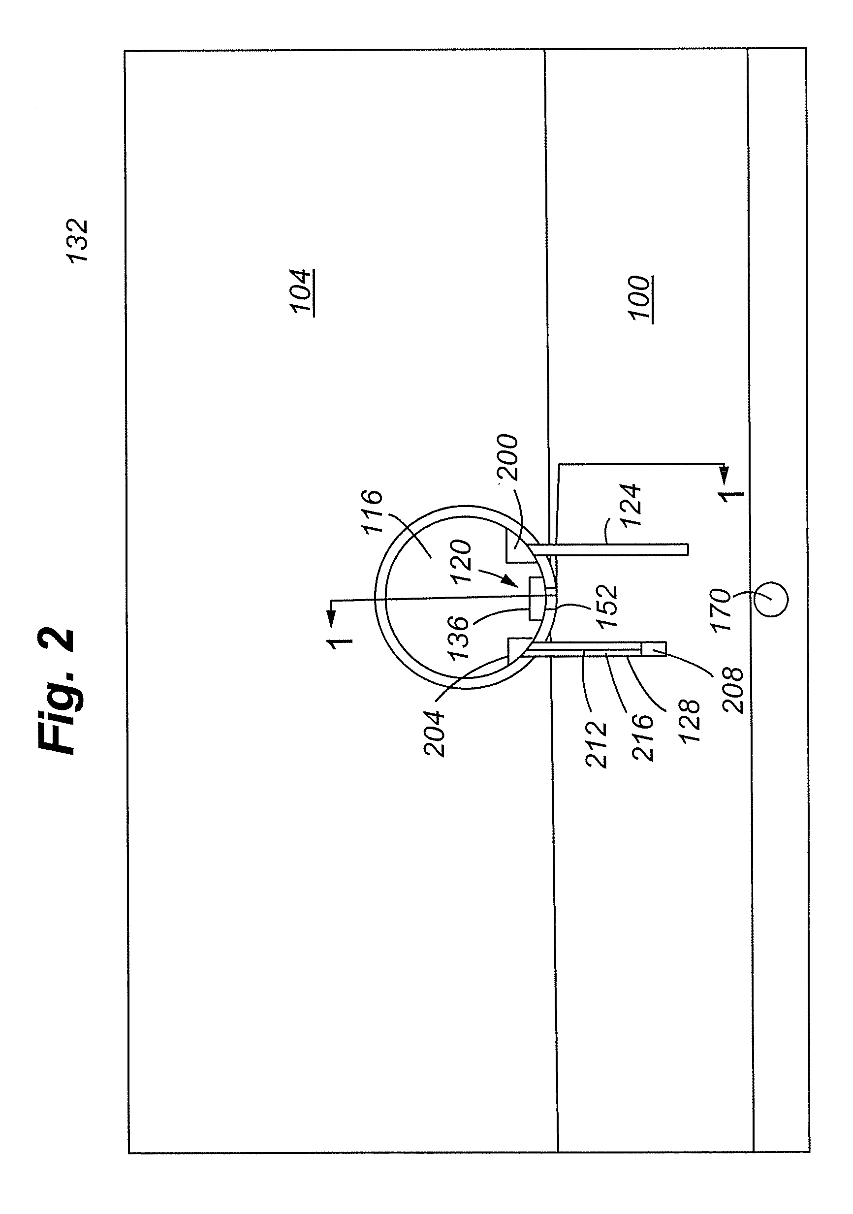
"The present invention provides a method for recovering hydrocarbon-containing materials from subterranean formations using electromagnetic and acoustic stimulation techniques. The invention allows for direct human access to the formation, thereby removing obstacles related to downhole drill string. The invention can reduce the viscosity of the hydrocarbon-containing material, making it easier to flow through the formation matrix. The use of manned excavations and selective stimulation can reduce the energy required to produce a barrel of hydrocarbon-containing material. The invention can also use horizontal wellbores for hydrocarbon collection, which was previously not possible with conventional techniques."

Problems solved by technology

The waveguide, however, at the only available, relevant microwave frequency is still far too large to fit within any standard well casing.
In general, RF thermal stimulation techniques have encountered several pitfalls.
These pitfalls include localized charring around the heating probes, limited field penetration, electrical downhole component failure, and the like.
Prior art techniques can have drawbacks.
The vertical string introduces several natural barriers which prevent the techniques from being commercially practical or at least introduces a large measure of additional cost or engineering difficulty related to energy loss and the necessity to locate the electrical equipment on the surface of the ground above the oil formation from where the energy must then be transmitted down a drill hole to access the oil formation.
The barriers include inaccessibility of the stimulation device(s) after being placed, well completion at the surface and downhole end, operational unreliability of the stimulation device(s) and repair difficulties from location of the device(s) in the well casing, difficulty in keeping potentially harmful and / or flammable liquids from the device(s), well casing incompatibility with the stimulation actuators, creation of a means at the bottom of the drill casing whereby the energy can be transferred into the formation, and inability to recover the installed hardware.
In particular, the limited size of standard drill casings, as well as the prohibitive cost of oversize casings, greatly restrict the size and complexity of components which can be reliably placed therein.
Moreover, heat can be lost heating up country rock and groundwater in proximity to the reservoir.
Vertical hydrocarbon removal can raise recovery costs and lower recovery of hydrocarbons due to the pumping pressure and / or drive pressure (such as from steam introduced into the reservoir) required to overcome the effect of gravity.
Prior art techniques are generally unable to recover more than approximately 20% of the heavy oil in place, resulting in an overall inefficiency and loss of resource potential.

Method used


Image

  • Stimulation and recovery of heavy hydrocarbon fluids
  • Stimulation and recovery of heavy hydrocarbon fluids
  • Stimulation and recovery of heavy hydrocarbon fluids

Examples


example 1

[0096]Extensive computer reservoir modeling analyses were conducted for several heavy oil scenarios in Cold Lake, Alberta, Canada to evaluate the expected performance of microwave stimulation. The reservoir parameters are as follows:

Pay zone thickness20 mPorosity0.35Permeability2,200 mdRes. Temperature13 degrees CelsiusViscosity (live oil)22,000 cp @ 20 degrees Celsius950 cp @ 50 degrees Celsius43 cp @ 100 degrees CelsiusBHP500 kPaWater Saturation0.26Oil Saturation0.327Pore Volume0.446

[0097]A single vertical microwave (915 MHz) emitter was located in the center of a cylindrical test area with diameter 150 meters. Oil “recovery” was modeled as oil which reached the bottom of the test cylinder. The cylinder bottom coincided with the bottom of the pay zone. The simulation was run with 100 kW of microwave power for the first 150 days and 70 kW thereafter. Microwave power was switched on and off according to a set thermostat temperature of 300 degrees (max) to 280 degrees Celsius (minimu...

example 2

[0098]For the same Cold Lake reservoir parameters as in Example 1, a single microwave emitter (100 kW at 915 MHz) was located at the center of a 150 m by 150 m area directly above a horizontal recovery well, which was located at the bottom of the pay zone. The microwave power supply was thermostatically controlled as in Example 1. The simulation time was 10 years (FIGS. 5A and 5B). Average oil production was 3.28 cubic meters / day, and the cumulative recovery was 35.3%.

example 3

[0099]For the same Cold Lake reservoir arrangement as in Example 2, an arrangement of four vertical microwave emitters were positioned 25 m apart and along a horizontal recovery well. Each injector antenna provided 25 kW of microwave power at 915 MHz and the sources were thermostatically controlled as in Example 1. The simulation time was 10 years (FIG. 6). Average oil production rate was 4.80 cubic meters / day, and the cumulative recovery was 59.7%.

[0100]A number of variations and modifications of the invention can be used. It would be possible to provide for some features of the invention without providing others.

[0101]For example in one alternative embodiment, the surfactant is not injected into the formation 100 but is generated in situ by hydrous pyrolysis / partial oxidation of constrained organics, such as petroleum and petroleum products, including fuel hydrocarbons, polycyclic aromatic hydrocarbons, chlorinated hydrocarbons, and other volatile materials. The materials are cont...


PUM


Abstract

The present invention is directed to the use of electromagnetic radiation, acoustic energy, and surfactant injection to recover hydrocarbon-containing materials from a hydrocarbon-bearing formation.

Description

CROSS REFERENCE TO RELATED APPLICATION[0001]The present application claims the benefits of U.S. Provisional Application Ser. No. 60 / 827,012, filed Sep. 26, 2006, entitled “Means for the Stimulation and Recovery of Heavy Hydrocarbon Fluids”, and 60 / 867,537, filed Nov. 28, 2006, of the same title, each of which are incorporated herein by this reference.FIELD OF THE INVENTION[0002]The invention relates generally to recovery of hydrocarbon fluids and particularly to the in situ thermal stimulation and recovery of hydrocarbon fluids.BACKGROUND OF THE INVENTION[0003]Heavy and extra heavy oil and bitumen represent the largest deposit types of recoverable hydrocarbons in the world. As an example, the proven, recoverable heavy oil reserves (including oil sands) in Alberta, Canada are greater that all of the light oil reserves of the Middle East. As used herein, heavy and extra heavy oil refers to a hydrocarbon-containing material having an American Petroleum Institute (“API”) gravity, or spe...

Claims


Application Information

Patent Timeline
Patent Type & Authority Applications(United States)
IPC IPC(8): E21B43/22E21B43/16
CPCE21B43/2401E21B43/003
Inventor TRANQUILLA, JAMESPROVOST, ALLAN G.
Owner HW PROCESS TECH
Features
  • Generate Ideas
  • Intellectual Property
  • Life Sciences
  • Materials
  • Tech Scout
  • Unparalleled Data Quality
  • Higher Quality Content
  • 60% Fewer Hallucinations
Learn More