Apparatus for coating a pipe surface

a technology for pipes and apparatuses, applied in coatings, other domestic objects, manufacturing tools, etc., can solve the problems of affecting the performance of pipes, affecting the wear of pipes, and abrasives suspended in fluids, etc., to achieve fine angular positioning, reduce wear on the liners, and repeatable swap of components.

Active Publication Date: 2008-03-27
FLINT WEAR TECH LP
View PDF6 Cites 19 Cited by
  • Summary
  • Abstract
  • Description
  • Claims
  • Application Information

AI Technical Summary

Benefits of technology

[0102]In order to reduce wear on the liners at the torch the arrangement described herein may incorporate a water cooled torch with a robust wire guiding system.
[0103]The arrangement described herein uses a welding head manipulator arm which is attached to the support carriage that is designed specifically to ride along the guidance bar. Three independent axes of control allow for precise angular and radial positioning anywhere within the bottom 180 degrees of the pipe. Each axis uses a dedicated servo-motor and gearbox sized accordingly to accommodate anticipated payloads.
[0104]One servo-motor and gearbox is located at the “shoulder” of the arm and used to provide course angular positioning of the welding head tip. Another servo-motor gearbox combination is located at the “elbow” of the arm and works in conjunction with the shoulder motor to provide fine angular positioning as well as radial positioning. At the “wrist” of the arm the final servo-motor and gearbox provides precise welding head angle adjustment for the varying locations within the pipe.
[0105]With intelligent control of these three axes the welding head is able to be positioned accurately anywhere within the bottom 180 degrees of the pipe with no mechanical adjustments required. This allows the operators to weld and switch between either side of the pipe effortlessly.
[0106]The range of motion may be limited making it necessary to use different upper arms lengths to incorporate the entire range of pipe diameters that the machine must be able to work with. Three different length arms may be interchangeable in a manner that will allow for a fast, accurate, and repeatable swap of components. One arm may be used for pipes with inside diameters between 17 and 27 inches. Another may be used for pipes with inside diameters ranging from 27 to 37 inches and the final arm for pipes with inside diameters between 37 and 47 inches. Care may be taken to center the shoulder pivot point in the center of the pipe to allow for smooth, easy, and accurate angular placement of the welding head.
[0107]The carriage case may need to be open along the top to allow the middle guide bar support to pass unobstructed. This opening may be sealed through the use of brushes to allow the incorporation of some positive air pressure to help combat contamination of the rolling elements. The design may include a support mount for the manipulator arm as well as connections for the tie rod push mechanism.

Problems solved by technology

As the fluid passes through the pipe, frictional forces against the pipe walls can cause the pipe walls to wear.
Abrasives suspended within the fluid (e.g. solids commonly associated with mining slurries or sludge) can be even more detrimental to the pipe walls.
Whatever the cause, these forces cause the pipe walls to wear even faster, is eventually causing the pipe walls to crack or burst where the walls have worn thin.
Areas left unprotected will continue to be vulnerable to fracture.
It does however have a number of areas where problems can arise and where improvements are desirable.
This limits the travel distance because as the unsupported length of the bar is increased oscillation and deflection problems are encountered.
Instability in the support system can create two main obstacles to fast, efficient welding of the pipe elbows and S-bends.
This droop hinders the ability of the welder to complete a straight and even path through the pipe.
Furthermore, the larger the bend radius of the pipe, the greater the effect of droop has on the quality of the welds.
The current welding set-up is in some cases not stable enough to reliably produce fast and accurate welds in both directions of travel.
Instability can develop into an unintended oscillating motion of the welding head that is entirely incompatible with the welding process used to layer the pipe.
Due to the instability of the guiding system the operators generally can weld in one direction only.
This combined with difficulty to rapidly return to the starting weld position can dramatically affect the welding cycle time.
Within a welding environment there come a number of challenges.
However, a disadvantage of using the flexible member in Kostecki is the associated inaccuracy in translating the rotational steps along the longitudinally flexible member.
Because the coating means cannot be accurately rotated, the protective material can be misapplied resulting in either gaps or overlap between the applied strips of protective material.

Method used


Image

  • Apparatus for coating a pipe surface
  • Apparatus for coating a pipe surface
  • Apparatus for coating a pipe surface

Examples


Embodiment Construction

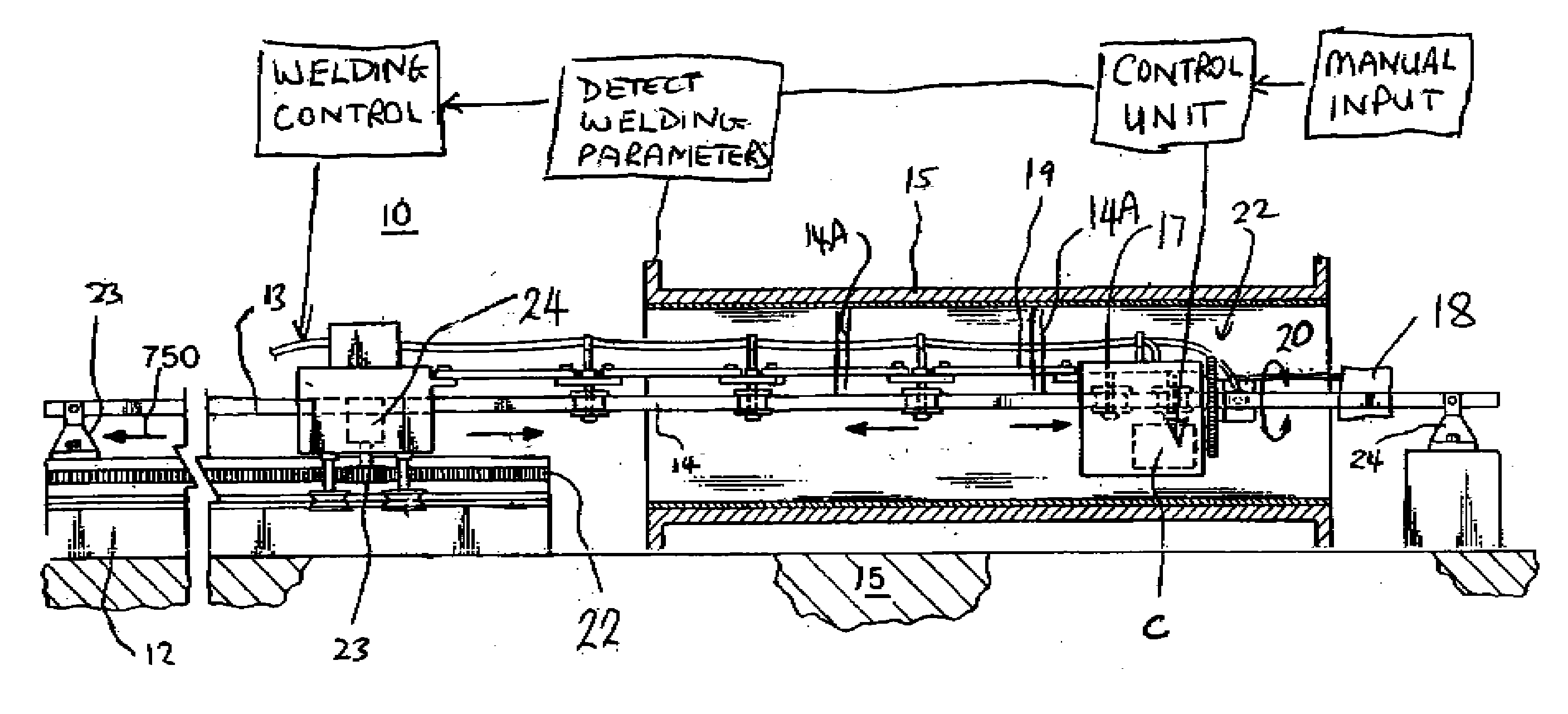
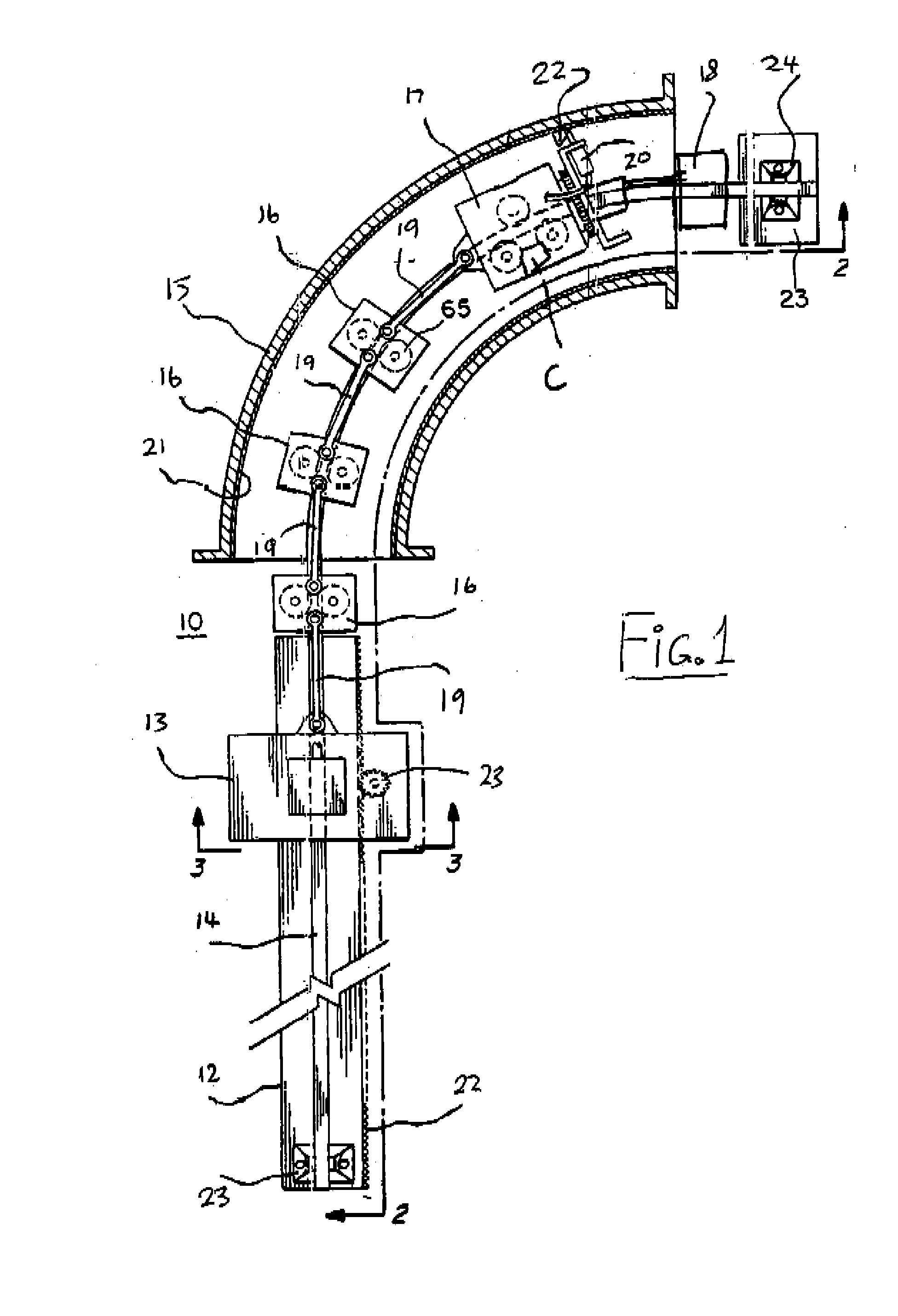
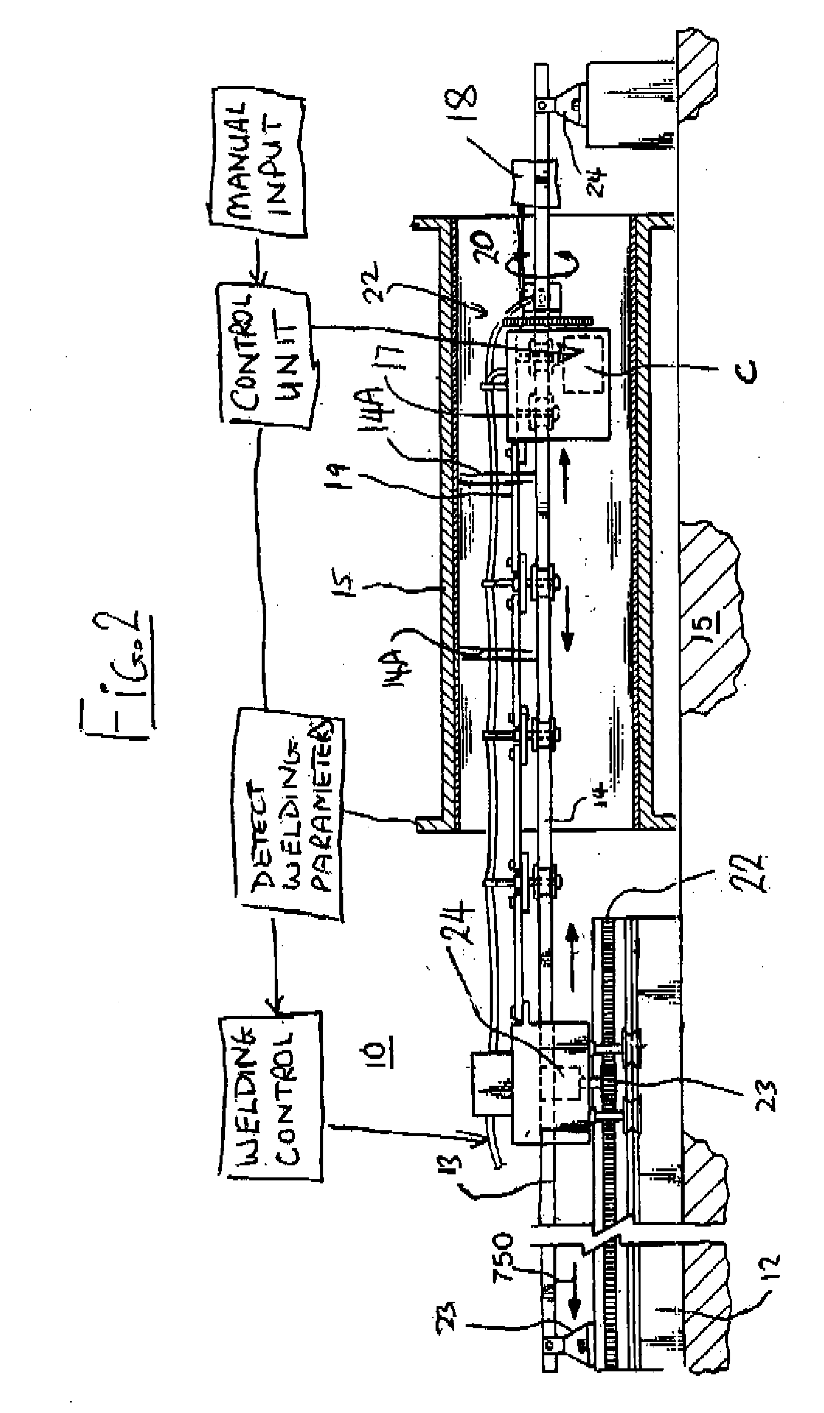
[0117]An apparatus 10 is shown In FIGS. 1 and 2 and includes a frame 12 supports a drive carriage 13 and a support rod 14. The support rod 14 extends along the length of the frame 12 and beyond the frame 12 above the floor 15 on which the frame stands so that the support rod 14 can be extended through a pipe generally parallel to the axis of the pipe. In FIG. 1, three intermediate carriages 16 and an operating carriage 17 are shown for movement along the support rod 14.

[0118]An additional support carriage 18 is provided in advance of the operating carriage 17 to provide support for components of the system including control cables and other elements as required which are to be supported at a position spaced from the operating carriage so as to keep them away from the operating components as described hereinafter.

[0119]The support rod 14 is shaped to provide support for the carriages as a train of carriages so that each carriage travels longitudinally along the support rod 14 in a fi...


PUM

PropertyMeasurementUnit
travel distanceaaaaaaaaaa
temperatureaaaaaaaaaa

Abstract

A wear resistant coating is applied on an elbow or S-bend by weld beads applied along a pipe. A rectangular support rod is attached inside the pipe by connectors so that wheels of the carriage are guided on the corners to maintain a fixed orientation relative to the support rod. A three axis robot arm carries an electric welding head so as to be able to dynamically adjust the head both angularly and radially. A welding wire is pulled to the head by a feeding system on the carriage. The weld parameters including a predetermined wire stick out and angle of wire attack are controlled. A drive motor carried by a drive carriage propels the drive carriage longitudinally along the support rod with a series of intermediate carriages.

Description

[0001]This application claims the benefit under 35 U.S.C. 119 of the filing date of Provisional Application Ser. No. 60 / 826,936 filed Sep. 26th 2006.[0002]The present invention relates generally to the field of apparatus for coating an inside surface of a pipe.BACKGROUND OF THE INVENTION[0003]Pipes are often used to carry fluids or abrasive slurries as part of a treatment or disposal process. As the fluid passes through the pipe, frictional forces against the pipe walls can cause the pipe walls to wear. The effect of these frictional to forces is magnified on the curved portions of the pipe as a result of complex flow patterns and the forces from the fluid impacting the pipe surface caused by the fluid changing direction. Abrasives suspended within the fluid (e.g. solids commonly associated with mining slurries or sludge) can be even more detrimental to the pipe walls. Whatever the cause, these forces cause the pipe walls to wear even faster, is eventually causing the pipe walls to ...

Claims


Application Information

Patent Timeline
Patent Type & Authority Applications(United States)
IPC IPC(8): B23K9/04
CPCB23K2201/06B23K9/048B23K2101/06
Inventor KOSSOWAN, BARRY
Owner FLINT WEAR TECH LP
Why Eureka
Try Eureka