Method and optical amplifier for laser safety protection and method for loading identification signal

a technology of optical amplifier and laser, applied in the direction of optical transmission, electromagnetic transmission, transmission monitoring, etc., can solve the problems of a greater possibility of harming human eyes, high laser density in the output direction, and a greater threat to human eyes, so as to achieve low implementation cost, no increase in optical amplifier cost, and simple implementation

Inactive Publication Date: 2008-03-27
HUAWEI TECH CO LTD
View PDF17 Cites 6 Cited by
  • Summary
  • Abstract
  • Description
  • Claims
  • Application Information

AI Technical Summary

Benefits of technology

[0048] Adding such a control function in the existing control mode of optical amplifier may load the identification signal on the main optical channel, and cost of the optical amplifier is not increased, thereby the implementing cost is low.
[0049] Because the identification signal is a low-frequency signal, the PIN diode at the input side of optical amplifier may also be used for detecting the identification signal as well as detecting the power, which makes implementation simple.

Problems solved by technology

Because of the excellent directivity of laser, the power density of laser in the output direction is especially high, which greatly threatens human eyes.
Because it is invisible, the light beam has a greater possibility to hurt human eyes.
Such a high power of the optical signal greatly threatens safety of operators and maintenance personnel of telecommunication system.

Method used


Image

  • Method and optical amplifier for laser safety protection and method for loading identification signal
  • Method and optical amplifier for laser safety protection and method for loading identification signal
  • Method and optical amplifier for laser safety protection and method for loading identification signal

Examples


Embodiment Construction

[0057] Automatic Power Reduction (APR) is implemented by the adding of a link state detecting component and a laser output control component in an optical communication device. For example, the APR procedure of a common optical amplifier in an optical communication system is as follows.

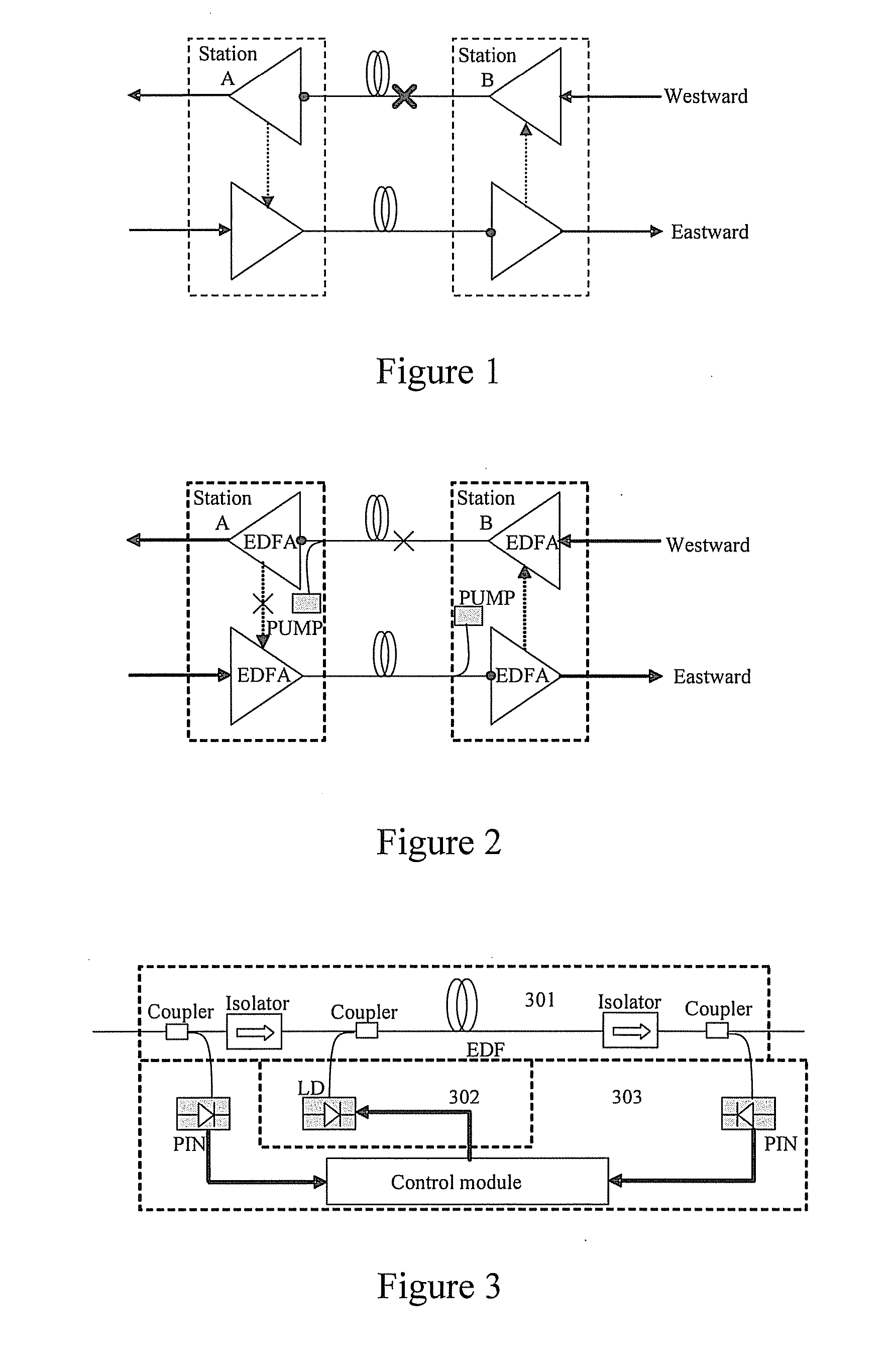
[0058] As shown in FIG. 1, if there is a potential laser leakage because of a failure on the westward fiber from station B to station A, the westward optical amplifier of station A will detect loss of the optical signal sent from station B by the link state detecting component, and determine that there is a potential laser leakage on the fiber from station B to station A. The potential laser leakage may also exist on the fiber from station A to station B. The westward optical amplifier of station A will notify the eastward optical amplifier of station A to reduce the output power to make the laser leakage on the fiber from station A to station B be compatible with the safety level constituted by Stan...


PUM


Abstract

A method for laser safety protection in an optical communication system includes: a downstream station detecting whether an identification signal loaded by an upstream station on a main optical channel in a direction from the upstream station to the downstream station, exist on the main optical channel; if the identification signal is not detected, the downstream station executing a scheduled safety protection procedure. Methods for loading an identification signal on a main optical channel in an optical communication system and an optical amplifier of laser safety protection, which implement loading the identification signal by controlling the change of pump light of optical amplifier or the wave motion of signal light of main optical channel, are also provided. The solution makes it possible to reliably detect a fiber failure when RAMAN amplifiers or remotely-pumped amplifiers exist, thereby implementing laser safety protection.

Description

CROSS REFERENCE TO RELATED APPLICATIONS [0001] This application is a continuation of International Patent Application No. PCT / CN2006 / 001192, filed Jun. 2, 2006, which claims priority to Chinese Patent Application No. 200510074888.4, filed Jun. 3, 2005, both of which are hereby incorporated by reference. FIELD OF THE INVENTION [0002] The present invention relates to optical network communication technology, and more particularly, to a method and an optical amplifier for laser safety protection in an optical communication system and methods for loading an identification signal on a main optical channel. BACKGROUND OF THE INVENTION [0003] Because of the excellent directivity of laser, the power density of laser in the output direction is especially high, which greatly threatens human eyes. The wavelength of lasers used in the existing communication system is generally around 870 nm, 1310 nm and 1550 nm, which are all beyond the wavelength range of a visible light. Because it is invisib...

Claims


Application Information

Patent Timeline
Patent Type & Authority Applications(United States)
IPC IPC(8): H04B10/08H04B10/077
CPCH04B10/0771H04B2210/074H04B2210/08H04B10/0777
Inventor WANG, HAOLU, YIQUANLI, CONGQI
Owner HUAWEI TECH CO LTD
Why Eureka
Try Eureka