System and methods for inserting a spinal disc device into an intervertebral space

a technology of spinal discs and intervertebral space, which is applied in the field of system and methods for inserting spinal disc devices into intervertebral space, can solve the problems of sciatica or pain, urinary and fecal incontinence, and inability to move, so as to achieve the effect of easy determination of the position of the disc devi

Inactive Publication Date: 2008-03-27
PIONEER SURGICAL TECH INC
View PDF87 Cites 114 Cited by
  • Summary
  • Abstract
  • Description
  • Claims
  • Application Information

AI Technical Summary

Benefits of technology

[0089]Another feature of the locking mechanism is a multiple-stepped groove path keeps the user from unintentionally releasing the trial spacer by requiring the user to position the locking mechanism in a position different from the other operating positions. Specifically, the depressible shaft must be depressed to release the spacer from the locking position. Once this is done, spacer may be pivoted to its desired orientation. Once the spacer has been pivoted to its 90 degree orientation, the groove path jogs transversely to the longitudinal axis and direction of travel of the piston. The transverse groove path extends longer than the initial transverse groove path disposed at the 0 degree orientation. This requires the user to depress the shaft substantially further than is required or allowed to release the locking mechanism at the 0 degree orientation. Thus, even if the surgeon holds the locking button down during rotation of the handle, he will have to depress the shaft significantly beyond its position during travel of the spacer between 0 and 90 degrees. Because the user must depress the shaft substantially further to move the locking mechanism into a trial spacer relea

Problems solved by technology

Although many factors may be responsible for causing lower back pain, a principal factor is damage or degeneration of an intervertebral spinal disc resulting in impingement on the nerve system, specifically the spinal cord, located within the spine.
Such impingement may result in, for instance, loss of mobility, urinary and fecal incontinence, and sciatica or pain experienced in the extremities.
Damage to or degeneration of a spinal disc can result from a number of factors such as abuse or age.
Most frequently, disc degeneration results from damage occurring to the annulus such that the flowable nucleus material may leak or seep out of the annulus.
Disc degeneration also can occur in other ways, such as by being deprived of nutrient flow leading to a dried disc susceptible to damage.
However, the current practice of each of these procedures typically has certain limitations.
With fusion, making a portion of the spine generally rigid produces a reduction in mobility, and drastically alters normal load distribution along the spinal column.
The increased stress and strain on the non-fused portions may lead to accelerated disc degeneration of the non-fused portions, particularly the adjacent levels of the spine.
However, current discectomy often may lead to a reduction of the disc space between adjacent vertebrae, as well as instability in the affected portion of the spine.
Such long-term effects with current discectomy often result in further surgery several years after the initial discectomy surgery.
However, little success has been experienced with prosthetic disc implants due to the complexity of the natural disc structure and biomechanical properties of a natural spinal disc.
In using disc implants, one problem relates to the preparation for the surgical procedure for implanting either the TDPs or DNPs.
Extra time is wasted when an implant has otherwise similarly configured ends such that it is diffic

Method used


Image

  • System and methods for inserting a spinal disc device into an intervertebral space
  • System and methods for inserting a spinal disc device into an intervertebral space
  • System and methods for inserting a spinal disc device into an intervertebral space

Examples


Embodiment Construction

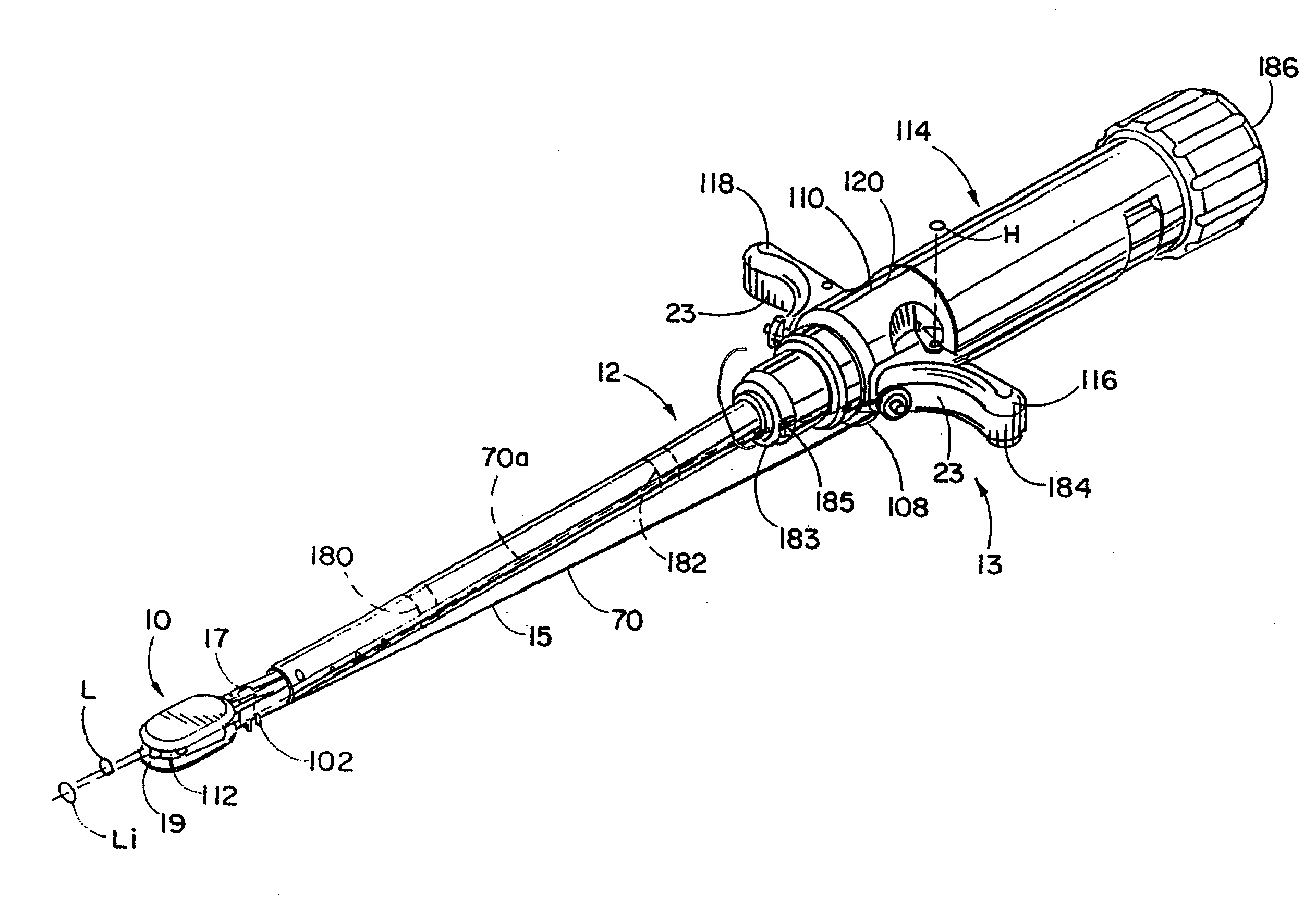
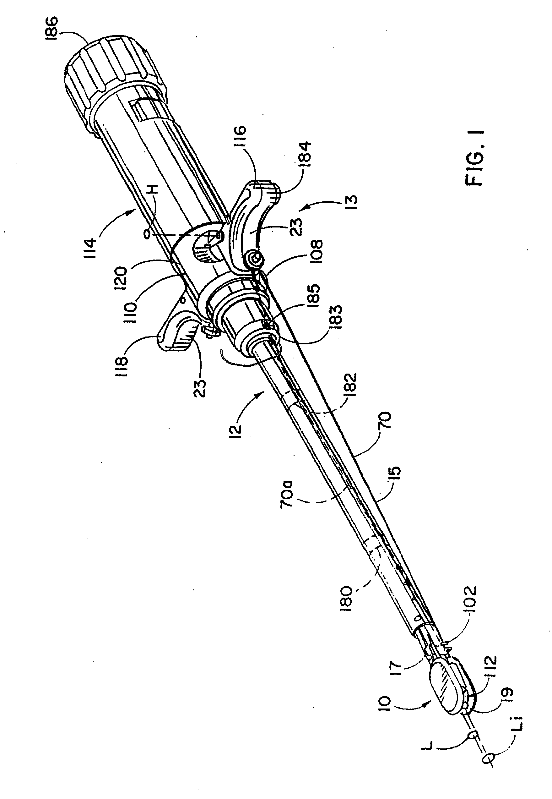
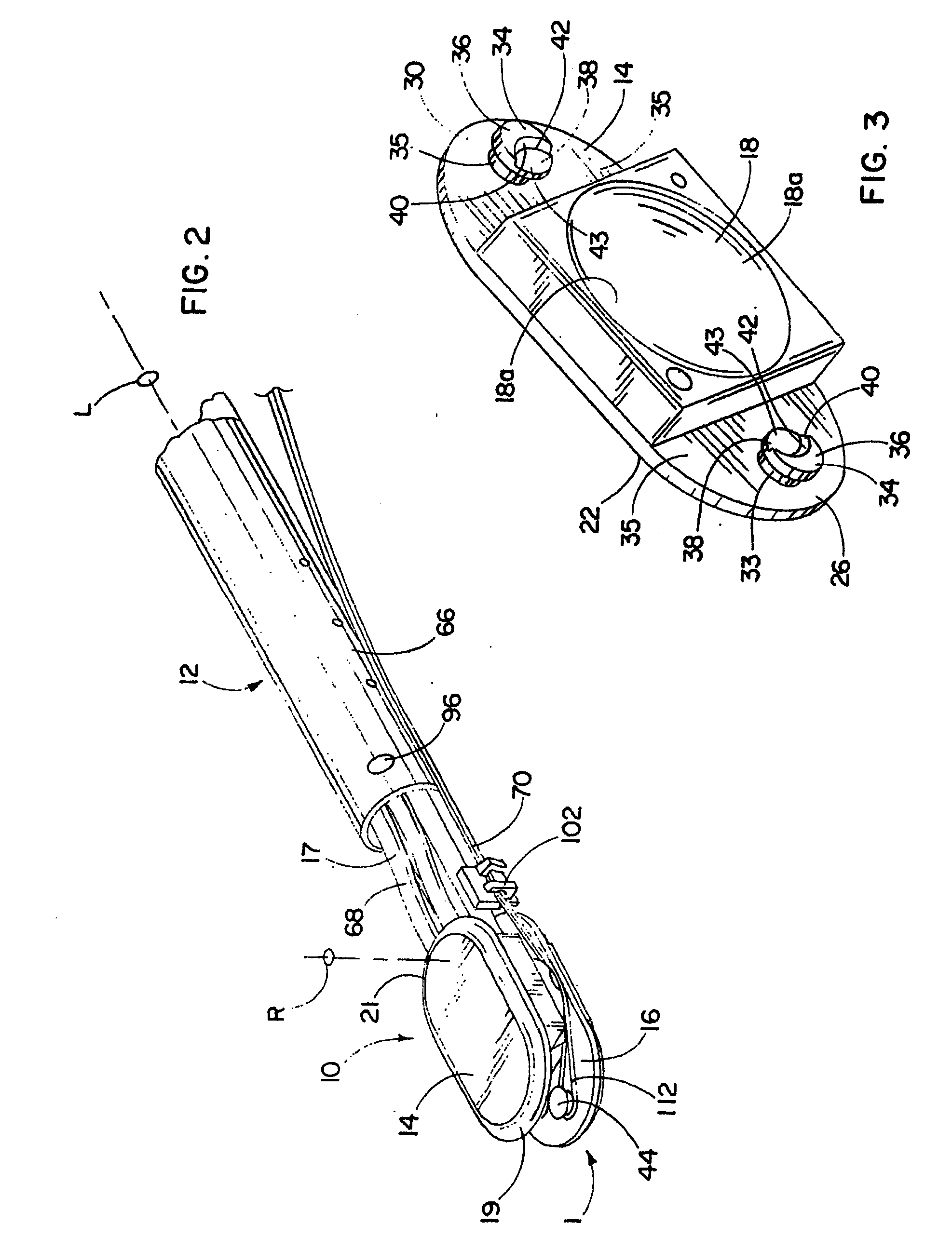
[0182]Referring to FIGS. 1 and 2, a spinal implant 10, such as an artificial disc, is mounted on or connected to an inserter tool 12 for replacing a nucleus of a natural spinal disc between adjacent vertebrae preferably without removing the annulus surrounding the nuclear space. In order to minimize the size of the incision in the annulus, the implant 10 should be inserted by leading with its narrow side facing the incision and pivoting the implant once the implant is positioned within the nuclear space in order to place the implant with its longitudinal dimension or axis Li extending orthogonal to the posterior-anterior direction (i.e. lateral relative to the spine). To pivot the implant 10 without significantly pushing against the incision, which could enlarge or otherwise damage the incision, the inserter 12 has a distal end 17 that extends into the nuclear space and holds the implant 10 while cooperating structure 11 on the inserter 12 and implant 10 are configured to pivot the ...


PUM


Abstract

A system for replacing a natural nuclear disc in an intervertebral space has a spinal device configured for placement in the intervertebral space. An insertion tool is configured for holding the spinal device while the spinal device is inserted into the intervertebral space. A gripping member of the insertion tool has an end for adjustably holding the spinal device within the intervertebral space. A steering actuator of the insertion tool is operably connected to the spinal device and configured for pivoting the adjustably held spinal device within the intervertebral space while the steering actuator is controlled remotely from the intervertebral space. The steering actuator is rotatable about a longitudinal axis of the tool. A locking mechanism is provided to keep the spinal device from pivoting in an insertion position and to keep the disc device from being released unintentionally.

Description

CROSS REFERENCE TO RELATED APPLICATIONS[0001]This application claims the benefit of U.S. Provisional Application No. 60 / 846,859, filed Sep. 22, 2006, all of which is hereby incorporated by reference as if reproduced herein in its entirety.FIELD OF THE INVENTION[0002]The present invention relates to artificial intervertebral implants and the tools to place the implants between vertebra, and in particular, to a steerable spinal disc device for placement of a sizing device or implant into an intervertebral space.BACKGROUND OF THE INVENTION[0003]The most common orthopedic condition for which professional medical treatment is sought is lower back pain. Although many factors may be responsible for causing lower back pain, a principal factor is damage or degeneration of an intervertebral spinal disc resulting in impingement on the nerve system, specifically the spinal cord, located within the spine. Such impingement may result in, for instance, loss of mobility, urinary and fecal incontine...

Claims


Application Information

Patent Timeline
IPC IPC(8): A61B17/58
CPCA61B2017/0256A61F2/4425A61F2/4611A61F2/4684A61F2002/30125A61F2002/30462A61F2250/0006A61F2002/30538A61F2002/4627A61F2002/4628A61F2220/0025A61F2220/0075A61F2230/0008A61F2002/30476
Inventor PERNSTEINER, WESTONTRUDEAU, JEFFREY
Owner PIONEER SURGICAL TECH INC
Why Eureka
Try Eureka