
Wet Active Chevron Nozzle For Controllable Jet Noise Reduction

a technology of active chevrons and chevrons, which is applied in the direction of efficient propulsion technologies, mechanical equipment, machines/engines, etc., can solve the problems of congestion at existing airports, affecting the growth of air transportation systems, and generating noise of aircraft, so as to reduce noise, reduce noise, and reduce noise

Inactive Publication Date: 2008-04-03
NASA
View PDF51 Cites 42 Cited by
  • Summary
  • Abstract
  • Description
  • Claims
  • Application Information

AI Technical Summary

Benefits of technology

[0011]It is another object of the present invention to provide an improved method of reducing noise utilizing fluid injection at least partially into a flow path from the nozzle surface.
[0012]It is another object of the present invention to provide an improved method of reducing noise by utilizing a method and device for injecting fluid, such as water, in a controlled manner so that the introduction or ceasing of the fluid input can be controlled under various circumstances.
[0013]It is yet another object of the present invention to provide a noise reduction system that can be secured and / or reduced at times to increase the efficiency of an aircraft engine, and thus help the aircraft achieve its maximum performance.
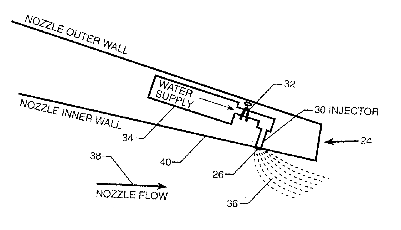
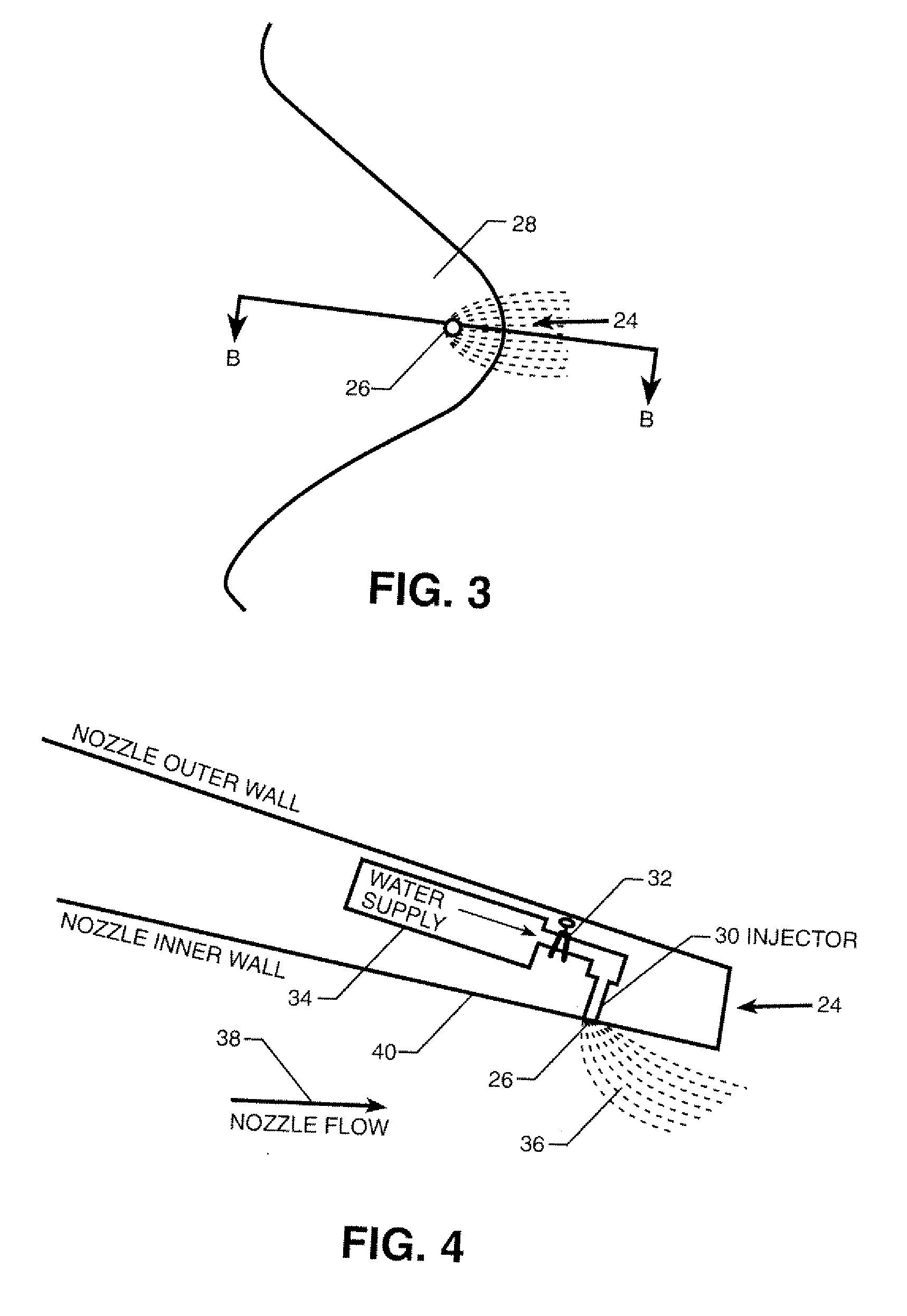
[0015]Accordingly, a fluid injection system is disposed toward the trailing edge of nozzles and configured to selectively inject fluid to penetrate into the flow so as to provide a selectively activateable chevron or extension there from. The momentum from water can simulate the effect of chevrons while providing the additional perceived benefit that water atomization can also contribute to additional noise suppression.
[0017]Additionally, as will be explained in more detail herein, it is within the scope of the present invention to utilize these injection ports on nozzles both with, or without, fixed chevrons. However, on a nozzle having fixed chevrons (i.e., a chevron nozzle), by using the water injection during aircraft takeoff to generate axial vorticity and thereby mix the fan and core streams (or the fan and free stream flows), the water augments the mixing from the fixed chevrons (resulting in what can be termed a “wet chevron”) such that a lower penetration fixed chevron can be used and therefore a correspondingly reduced cruise thrust performance loss can be realized.
[0019]As an added benefit, introducing fluid into the flow can produce additional noise suppression by mixing with the jet plume downstream and reducing turbulent and temperature fluctuations that can cause far-field noise radiation. An additional benefit of introducing the fluid would be some reduction in the infra-red signature of the typically high temperature jet plume. Further, because the water penetration can be inactivated during flight, during high noise activities, such as takeoff, the water can be made to penetrate deeper into the stream of flow than conventional chevrons, thus potentially reducing even more noise than previously possible.

Problems solved by technology

Aircraft generated noise has had a negative impact on the general public.
This negative impact has at times constrained the growth of the air transport system due to the objections frequently raised when the construction of a new airport is proposed.
This constraint on growth contributes to congestion at the existing airports.
The jet noise component of aircraft engine noise continues to be a significant source of noise even on recent high bypass ratio engine designs.
When designing aircraft, performance, maintenance and cost of use place stringent requirements on systems and modifications made to engines.
Therefore, devices and methods for noise control are typically subjected to these same constraints.
Therefore, the chevron shape, size and positioning (i.e., degree of penetration into the flow stream) are normally optimized for noise reduction at takeoff, however, this chevron design typically results in a corresponding negative result by causing excess drag during cruise.
Another noise reduction technique that has been previously studied, but apparently never implemented for flight applications, was water injection into the jet exhaust plume.
Therefore, while the known art has included efforts to use water injection into jet plumes to reduce noise, nevertheless, no effort is known by the applicant to use the momentum of water jets to also emulate the effects of fixed chevrons.

Method used


Image

  • Wet Active Chevron Nozzle For Controllable Jet Noise Reduction
  • Wet Active Chevron Nozzle For Controllable Jet Noise Reduction
  • Wet Active Chevron Nozzle For Controllable Jet Noise Reduction

Examples


Embodiment Construction

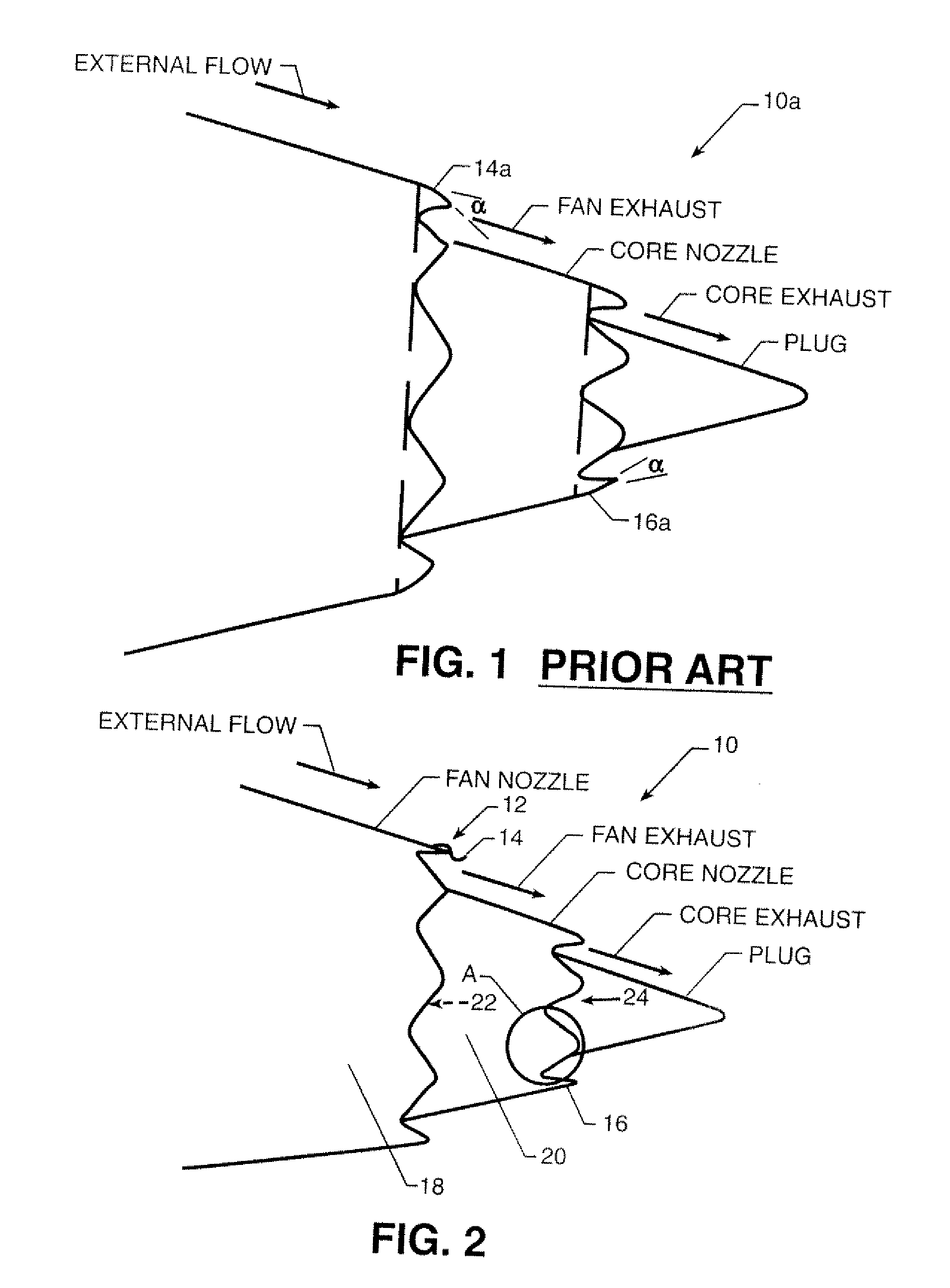
[0027]FIG. 1 shows a portion of a known jet engine 20 in which mechanically fixed chevrons, such as chevrons 14a and 16a, extend to penetrate into the stream of flow. FIG. 2 shows a portion of an engine 10 having a noise reduction system 12 constructed in accordance with at least one embodiment of the present invention. In briefly examining FIG. 1 and FIG. 2, there may not appear to be many differences. However, one will see that angle alpha ({acute over (α)}) exists in FIG. 1 as it relates to an angle that the chevrons, such as chevrons 14a and 16a, are directed into a flow path in this known nozzle design, as compared to the embodiment of the present invention which is depicted in FIG. 2. While this feature (i.e., angling the chevrons into the flow path) has been found to reduce noise at startup, unfortunately, it has also been found to reduce efficiency at cruise speed. Accordingly, as shown in FIG. 2, one can observe that chevrons in accordance with at least one embodiment of th...


PUM


Abstract

Disposed at or toward the trailing edge of one or more nozzles associated with a jet engine are injection ports which can selectively be made to discharge a water stream into a nozzle flow stream for the purpose of increasing turbulence in somewhat of a similar fashion as mechanically disposed chevrons have done in the known art. Unlike mechanically disposed chevrons of the known art, the fluid flow may be secured thereby increasing the engine efficiency. Various flow patterns, water pressures, orifice designs or other factors can be made operative to provide desired performance characteristics.

Description

ORIGIN OF THE INVENTION [0001]This invention was made by employees of the United States Government and may be manufactured and used by or for the Government for governmental purposes without the payment of any royalties thereon or thereof.FIELD OF THE INVENTION [0002]The present invention relates to methods and devices for reducing the jet noise component of aircraft engine noise, and more preferably to an improved selectively activated and controlled injection system which can be activated so as to reduce noise during high noise operations, such as at takeoff, and can be de-activated for maximum cruise performance, or other purposes.DESCRIPTION OF RELATED ART[0003]Aircraft generated noise has had a negative impact on the general public. This negative impact has at times constrained the growth of the air transport system due to the objections frequently raised when the construction of a new airport is proposed. This constraint on growth contributes to congestion at the existing airp...

Claims


Application Information

Patent Timeline
IPC IPC(8): F02C7/08
CPCB64D33/06F02K1/34F02K1/46F05D2260/232F05D2260/60F05D2250/70Y02T50/675Y02T50/60
Inventor THOMAS RUSSELL H.KINZIE KEVIN W.
Owner NASA
Learn More