Quartz crystal resonator

a crystal resonator and quartz crystal technology, applied in piezoelectric/electrostrictive/magnetostrictive devices, piezoelectric/electrostriction/magnetostriction machines, electrical apparatus, etc., can solve problems such as frequency-temperature characteristics that are deteriorated, and achieve excellent frequency-temperature characteristics, low cost, and reduced deterioration of frequency-temperature characteristics

Inactive Publication Date: 2008-04-03
SEIKO EPSON CORP +1
View PDF10 Cites 31 Cited by
  • Summary
  • Abstract
  • Description
  • Claims
  • Application Information

AI Technical Summary

Benefits of technology

[0012]In order to solve the problem described above, a quartz crystal resonator according to an aspect of the invention includes a quartz crystal resonator element having a main surface including an X axis (electrical axis) and a Z′ axis of an inclination rotated at an angle (y) equal to or greater than 36.4 degrees and equal to or smaller than 40.5 degrees from a Z axis (optical axis) around the X axis, a main vibrating portion vibrating at a predetermined resonance frequency (f) and a supporting portion integrally formed with the main vibrating portion in such a manner as to be formed peripherally to surround the main vibrating portion, and two covers having a thermal expansion coefficient equal to or greater than 6×10⁻⁶ per degrees centigrade and equal to or smaller than 10×10−6 per degrees centigrade and bonded to the supporting portion so as to sandwich the quartz crystal resonator element therebetween.
[0013]In the quartz crystal resonator according to the above aspect of the invention, a combination of a cut angle for cutting out a quartz crystal resonator element and a thermal expansion coefficient of the two covers within the above-mentioned range allows reduction in the deterioration of frequency-temperature characteristics even at environmental temperature changes. Consequently, the quartz crystal resonator can have excellent frequency-temperature characteristics.
[0014]In addition, since a commonly-used glass such as blue plate glass can be used as the covers, casings for the covers can be prepared at low cost. Use of such low-cost casings enables manufacturing of a low-cost quartz crystal resonator.
[0015]Furthermore, preferably, each of the two covers has a protruding portion formed peripherally thereon in such a manner as to roughly oppose the supporting portion, and the protruding portion is bonded to the supporting portion.
[0016]In this manner, the protruding portions of the two covers are bonded to the supporting portion of the quartz crystal resonator element, so that spaces can be provided between the main vibrating portion of the quartz crystal resonator element opposing parts excepting the protruding portions and the two covers. Consequently, the two covers do not disturb vibration of the main vibrating portion of the quartz crystal resonator element, and thus, for example, vibration characteristics such as a CI value and frequency characteristics obtained are excellent.
[0017]Furthermore, in this quartz crystal resonator, preferably, a circuit section including an oscillation circuit for the quartz crystal resonator element is provided on a surface of at least one of the two covers to be connected to the quartz crystal resonator element.

Problems solved by technology

Therefore, there arises a so-called problem that frequency-temperature characteristics are deteriorated.

Method used


Image

  • Quartz crystal resonator
  • Quartz crystal resonator
  • Quartz crystal resonator

Examples


first embodiment

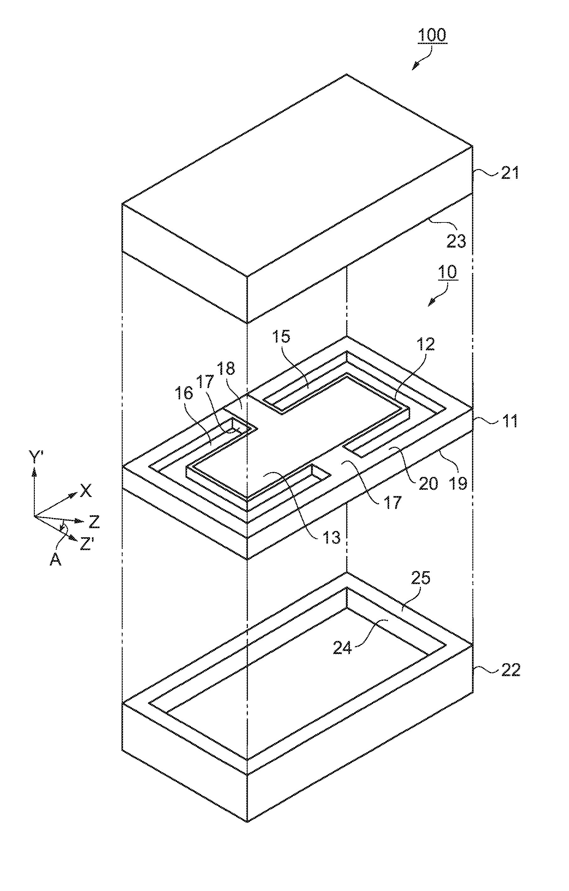
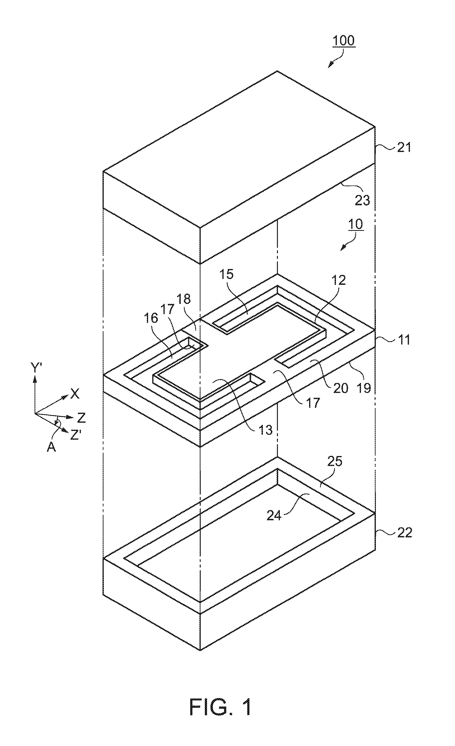
[0049]A quartz crystal resonator according to a first embodiment of the invention will be described by referring to FIGS. 1 and 2. FIG. 1 is a perspective view showing an outlined structure of the quartz crystal resonator according to the first embodiment, FIG. 2 is a sectional view of the quartz crystal resonator shown in FIG. 1.

[0050]As shown in FIGS. 1 and 2, a quartz crystal resonator 100 is comprised of a quartz crystal resonator element 10, first and second casings 21 and 22 as two covers sandwiching and covering the quartz crystal resonator element 10 from upper and lower sides thereof. The quartz crystal resonator 100 having such a structure is also called a CSP (Chip Size Package) resonator.

[0051]The quartz crystal resonator element 10 is comprised of a main vibrating portion 12 integrally formed from a quartz crystal substrate and a supporting portion 11 formed peripherally so as to surround the main vibrating portion 12 in a manner including an outer peripheral edge there...

second embodiment

[0078]A quartz crystal resonator according to a second embodiment of the invention will be described by referring to FIG. 6. FIG. 6 is a sectional view showing an outlined structure of the quartz crystal resonator according to the second embodiment.

[0079]As shown in FIG. 6, a quartz crystal resonator 110 is comprised of a quartz crystal resonator element 10, first and second casings 21 and 22 as two covers sandwiching and covering the quartz crystal resonator element 10 from upper and lower sides thereof and a circuit section 70 provided on a surface of the second casing 22. Here, the quartz crystal resonator 110 and the first and second casings 21 and 22 have the same structures as those in the first embodiment and thus are given the same numerals to omit explanation thereof.

[0080]The circuit section 70 is comprised of a semiconductor circuit element, etc., and at least serves to oscillate the quartz crystal resonator 110. The circuit section 70 is, for example, extended from the e...

modified example 1

[0084]As shown in FIG. 7, a quartz crystal resonator 113 is comprised of the quartz crystal resonator element 30, the first and second casings 38 and 39 as two covers sandwiching and covering the quartz crystal resonator element 30 from upper and lower sides thereof and the circuit section 70 provided on a surface of the second casing 39. Here, the quartz crystal resonator 113, the first and second casings 38 and 39 have the same structures as those of the modified example 1 in the first embodiment and thus are given the same numerals to omit explanation thereof

[0085]The circuit section 70 is comprised of a semiconductor circuit element, etc. and at least serves to oscillate the quartz crystal resonator 113. The circuit section 70 is, for example, extended from the excitations 33 and 33a of the quartz crystal resonator element 30 by the connection pad 71 such as an Au bump to be connected to connection electrodes 77 and 78 extendedly provided on an outer surface of the second casing...


PUM


Abstract

A quartz crystal resonator includes a quartz crystal resonator element having a main surface including an X axis (electrical axis) and a Z' axis of an inclination rotated at an angle (y) equal to or greater than 36.4 degrees and equal to or smaller than, 40.5 degrees from a Z axis (optical axis) around the X axis, a main vibrating portion vibrating at a predetermined resonance frequency (f) and a supporting portion integrally formed with the main vibrating portion in such a manner as to be formed peripherally to surround the main vibrating portion, and two covers having a thermal expansion coefficient equal to or greater than 6x10⁻⁶ per degrees centigrade and equal to or smaller than 10x10-6 per degrees centigrade and bonded to the supporting portion so as to sandwich the quartz crystal resonator element therebetween.

Description

BACKGROUND[0001]1. Technical Field[0002]The present invention relates to a quartz crystal resonator in which a quartz crystal resonator element has a main vibrating portion integrally formed with a supporting portion and is covered with casings of glass or the like.[0003]2. Related Art[0004]The recent trend toward smaller and thinner electronic equipment requires smaller and thinner designs of quartz crystal resonators incorporated therein. For the purpose of reducing the size and thickness of a quartz crystal resonator, for example, Japanese Patent No. 3390348 and JP-A-2006-157369 have disclosed a structure of a quartz crystal resonator (which is called a chip size package (CSP) quartz crystal resonator).[0005]Referring to FIG. 16, a description will be given of the above quartz crystal resonator. FIG. 16 is a front sectional view showing an AT-cut quartz crystal resonator using a quartz crystal substrate, as an example of the well-known quartz crystal resonator.[0006]A quartz crys...

Claims


Application Information

Patent Timeline
Patent Type & Authority Applications(United States)
IPC IPC(8): H01L41/00
CPCH03H9/02023H03H9/0547H03H9/1035H03H9/08H03H9/0595
Inventor YONG, YOOK-KONGPATEL, MIHIR S.TANAKA, MASAKO
Owner SEIKO EPSON CORP
Why Eureka
Try Eureka