Brushless DC permanent magnet motor

a permanent magnet motor and brushless technology, applied in the direction of motor/generator/converter stopper, dynamo-electric converter control, dynamo-electric gear control, etc., can solve the problems of need for a rotor position sensing device and its attendant cost, and achieve the effect of reducing the number of components, reducing manufacturing costs, and reliability of operation

Inactive Publication Date: 2008-04-03
ELECTRIC MOTORS & SPECIALTIES
View PDF10 Cites 5 Cited by
  • Summary
  • Abstract
  • Description
  • Claims
  • Application Information

AI Technical Summary

Benefits of technology

[0008]In summary, the overall simplicity and reduced number of components used in the disclosed motor system result in potential savings in manufacturing costs and reliability of operation.

Problems solved by technology

The position calculator feature obviates the need for a rotor position sensing device and its attendant cost.

Method used


Image

  • Brushless DC permanent magnet motor
  • Brushless DC permanent magnet motor
  • Brushless DC permanent magnet motor

Examples


Embodiment Construction

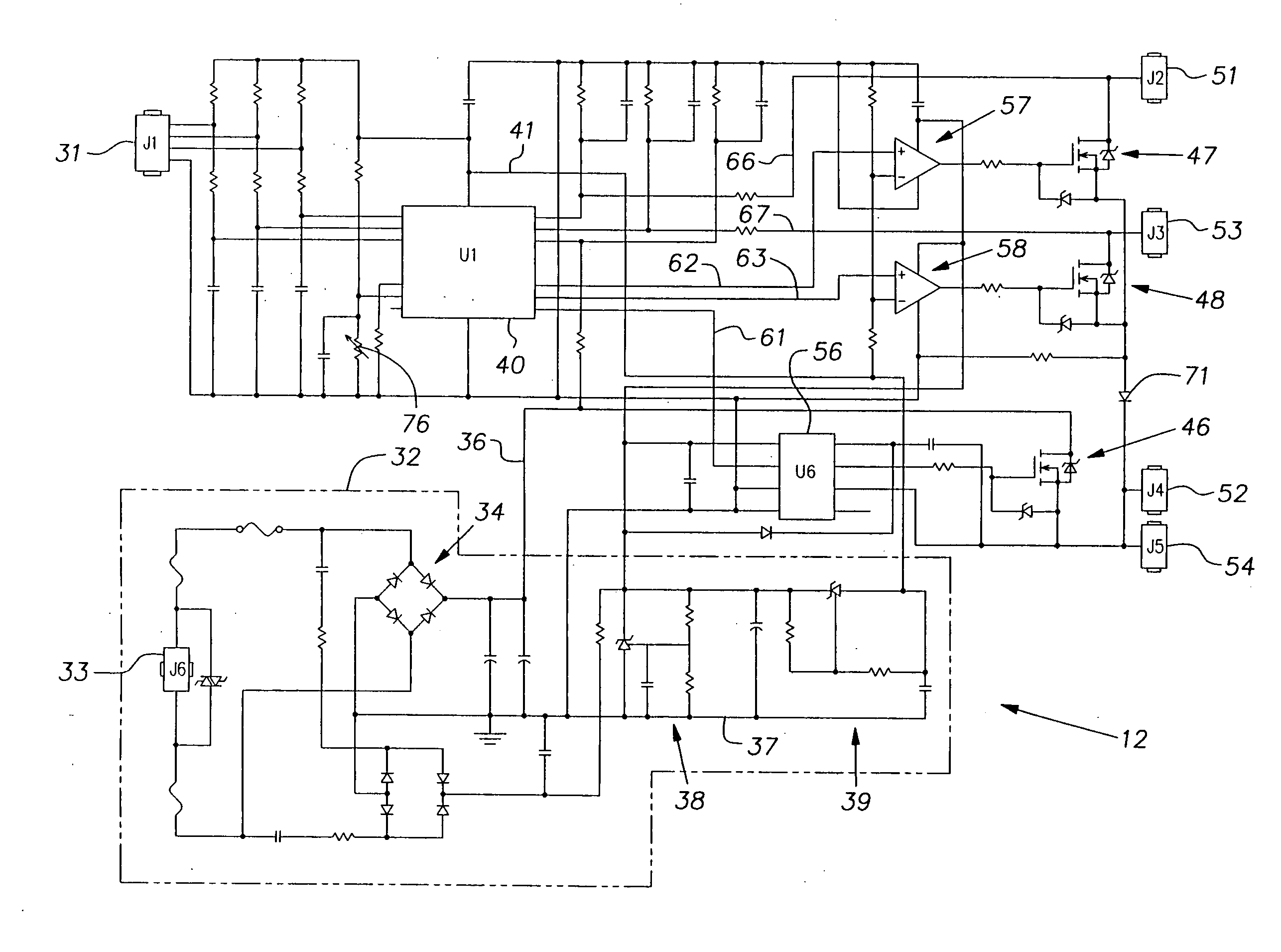
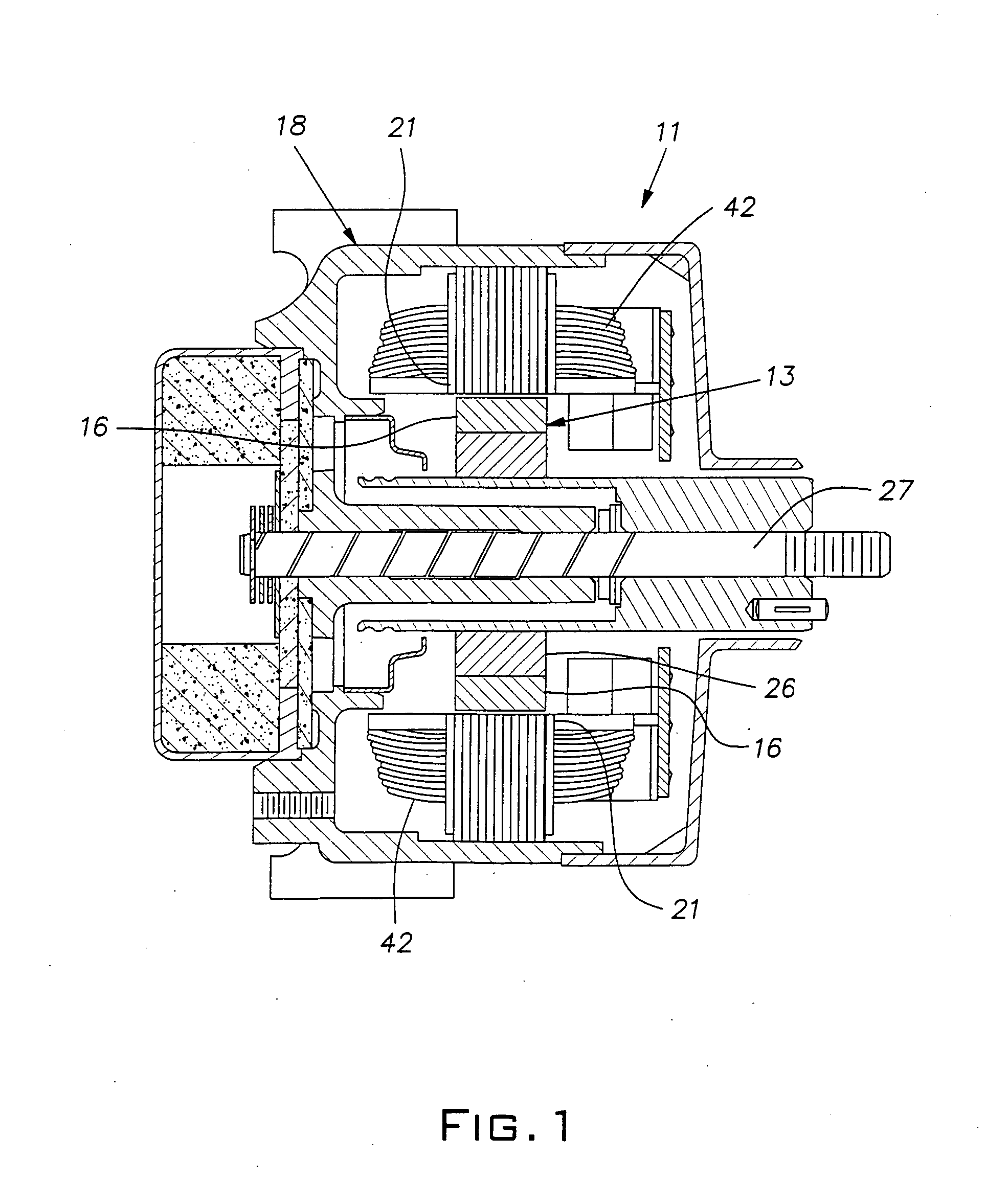
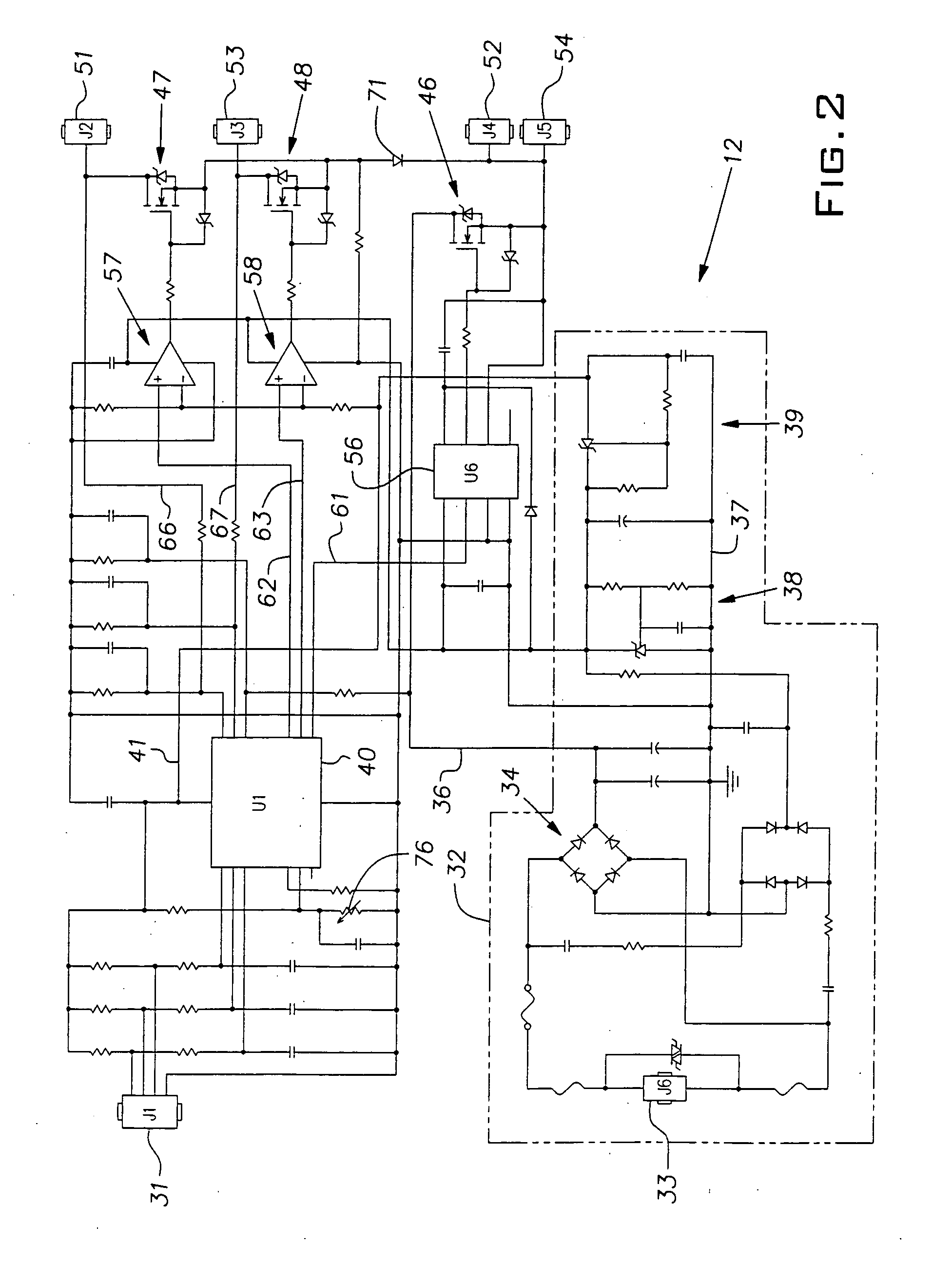
[0015]A system embodying the invention comprises an electrical motor 11 (FIG. 1) operated by an electronic control circuit 12 (FIG. 2). The illustrated motor 11 is a brushless permanent magnet type operating on direct current (DC). In the illustrated case, the motor 11 has a permanent magnet rotor 13 with four magnetic poles, 16, 17, and a stator 18 with four field poles 21, 22. The four rotor permanent magnets or poles 16, 17 are bonded to a ferromagnetic round tube 26 suitably supported for rotation about a central axis 27 by a bearing such as a unit bearing known in the art. The rotor magnets 16, 17 are oriented with their north and south poles alternating circumferentially about the axis 27.

[0016]Diametrically opposite pairs of stator poles 21 or 22 are electrically wound and interconnected in a manner that when simultaneously energized with direct current, they produce magnetic fields oriented in the same direction. That is, at the inside diameter of the stator 18 when one pole...


PUM


Abstract

A brushless DC motor operated by a microcontroller has a unique pole construction that enables it to reliably start and operate as a unipolar device so that a reduced number of electronic power switches can be used to reduce cost and complexity. The microcontroller calculated rotor position to eliminate the need for a separate sensor and thereby further reduce manufacturing cost.

Description

[0001]The invention relates to fractional horsepower motors and, particularly, to the construction of a permanent magnet brushless DC motor.PRIOR ART[0002]Small electric motors such as shaded pole motors can be inexpensive to produce, but have relatively low efficiency. Many applications for such motors can be significantly benefitted from a motor with increased efficiency. An example of such an application is air circulation in a refrigeration system where inefficiency is compounded by the need to remove heat generated by the motor. U.S. Pat. Nos. 3,158,769, 3,959,678, 4,234,810 and 5,036,237 disclose examples of shaded pole motors useful in commercial refrigeration systems. Conventional brushless DC motors are known to achieve relatively high efficiency but involve increased componentry and manufacturing costs.[0003]There continues to be a need for improving the efficiency and reducing the manufacturing costs of small electric motors.SUMMARY OF THE INVENTION[0004]The invention rel...

Claims


Application Information

Patent Timeline
Patent Type & Authority Applications(United States)
IPC IPC(8): H02K11/00H02K17/10H02P21/00
CPCH02K29/03H02P6/18
Inventor ASHE, LESTER B.WOLF, SCOTT B.
Owner ELECTRIC MOTORS & SPECIALTIES
Why Eureka
Try Eureka